Hydrodynamic Focusing - Owen O'Connor, Svilen Kolev, Lily Perryclear
Hydrodynamic focusing is when a fluid of interest with a low flow rate is entered into a system of sheath fluid with higher flow rates. The fluid of interest is compressed by the sheath fluids. Compressed fluids have smaller diffusion lengths and as an effect, they see shorter mixing times [1].
Passive vs. Active Mixing
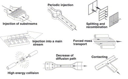
In microsystems energy can be applied to fluids to induce mixing using two major methods. Active mixing makes use of external energy input to create vibrations within the system. Energy sources used for this are ultrasound, magneto-hydrodynamic action, piezoelectric vibrating membranes, acoustic vibrations, and electro kinetic instabilities. Mixing can also be induced by methods of passive mixing, which uses energy from pumping and hydrostatic potential to modify aspects of fluid flow along channels to stretch streamlines and improve mixing. At the microscale turbulence is uncommon and flow after junctions often consists of separate lamellae. For this reason, considerations for mixing strategies are important. Complex flow patterns may be used to achieve complete mixing however it becomes difficult to model the fluid flows. For cases where the exact position and duration of mixing are of interest, it is desirable to achieve mixing without interfering with laminar flow since it can be modeled with high precision. This can be achieved with hydrodynamic focusing [2].
Hydrodynamic Focusing
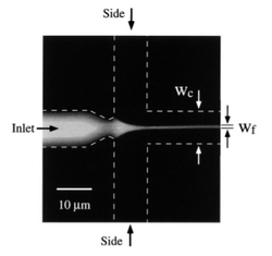
Hydrodynamic focusing is a way of controlling continuous flow mixing by confining streams to small geometries where mixing is dominated by diffusion. The major advantage of this mixing strategy is the achievement of very short complete mixing times while maintaining a highly controllable system which can be precisely modeled. In addition to knowing the distance and duration of mixing, the distance post mixing is proportional to time since the mixing point. In this system, there are three inlet streams: one central stream to be focused and two streams that converge perpendicularly to the central stream. This will cause the width of the central channel to decrease, increase the surface area and decrease the distance needed to travel for diffusion [4]. Figure 2 shows the principal of hydrodynamic focusing. This page covers hydrodynamic focusing in terms of passive mixing but it can also be used for flow cytometry and cell sorting, sensors and separation.
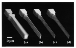
The important parameters here is the inlet pressures. In order to achieve narrow focusing of the inlet fluid, the side streams should have a higher pressure. The degree of focusing of the central lamella is not dependent on the applied pressure to the system but rather on the ratio of the pressures of the side channels to the central channel. In the literature is ratio is denoted by α = Ps/Pi. There is an upper and lower limit on the value of α for which focusing is effective. For a system with α > αmax the central stream is pinched off and the side channels flow into the inlet channel. For a system with α<αmin the central inlet is not focused but rather flows into the side streams. The parameters αmin and αmax are determined by the geometry of the system, and the overall magnitude of the pressure of the whole system. Figure 3 below shows the effect of α on the focusing stream.
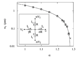
The system described by Knight et al. was modeled by an electric circuit, shown in Figure 4. In the analogy to an electric circuit, flow is driven by the voltage Vi (central inlet) and αVi (side inlets) and the channel resistance by R (side inlets) and γR (central inlet) and σR (outlet). The parameters γ and σ reflect differences in geometry and were determined analytically according to resistance to volumetric flow in rectangular channels. Sigma and gamma are used to determine αmin and αmax by the relationship αmin=σ/(σ+γ) and αmax=(1+2σ)/2σ. Figure 4 also contains a graph of width of focused channel (Wf)vs. α.
If the assumption is made that ratio of inlet fluid flux to outlet fluid flux is the same as the inlet current and outlet current in the circuit analogy, then an expression for the focusing width can be achieved: [math]\displaystyle{ \frac {Wf}{Wc} = \frac {B*(1+2σ-2σα)}{(1+2σγα)} }[/math] where Wf is the width of the focused lamellae and Wc is the width of the channel and B is a correctional constant that depends on channel geometry. This relationship provides the insight that increasing the resistance of the central inlet channel in relation to the side channel (increase γ) will result in a more focused stream. Knight et al. also did an analysis on the mixing time of their system. They found that [math]\displaystyle{ τmix= \frac {Wf^2 }{π^2 D} }[/math] where τmix is the time and D is the diffusion constant of the fluid being mixed. By increasing α to approach αmax, τmix approached 0. They found that a mixing time of 10 μs was easily reproducible [4].
Diffusional Mixing
Fick’s first law is an expression for the diffusive flux in terms of the concentration gradient and the diffusivity coefficient. Diffusional flux is the amount of a fluid that will flow through a unit area per unit time and is expressed as: [math]\displaystyle{ J = -D Δ C }[/math]. Observing Fick’s law it is apparent that microsystems are ideal for maximizing diffusional mixing.
The Reynolds number, Péclet number and the Fourier number are dimensionless quantities that are used to model convective or diffusive systems.
[math]\displaystyle{ Re = \frac {inertial forces}{viscous forces} = \frac {Ud}{μ} }[/math] where U is the average fluid velocity, d is the characteristic length, and μ is the viscosity of the fluid. With Re < 2100 flow is considered laminar.
[math]\displaystyle{ Pe = \frac {advective transport}{diffusive transport} = \frac {Ud}{D} }[/math] where D is the diffusional coefficient. At low Pe the mas transport is considered to be primarily diffusional as opposed to convectional.
[math]\displaystyle{ Fo = \frac {avg residence time}{diffusive mixing time} = \frac {Tr}{Tm} =\frac {L/U}{d2/D} }[/math] where L is longitudinal length [3].
Veenstra et al. demonstrated that the channel width may be decreased in order to increase mixing. The equation [math]\displaystyle{ t = \frac{pi\cdot x^1/2}{4\cdot D} }[/math] describes the time it takes for a particle to diffuse across a distance depending on the diffusion constant in 1-D [3].
The equation [math]\displaystyle{ l = \frac{t U}{h w} }[/math] (2) describes the necessary length, width and height for complete mixing where U is volumetric flow rate, l is length, w is width and h is height of the channel.
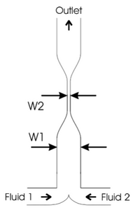
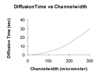
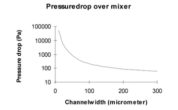
Therefore, when the distance (x) is decreased, the time needed for the particle to travel that distance (t) decreases too. As shown in Figure 5, two streams would be flown parallel into the same chamber and then the width of the channel will contract causing increased mixing. As shown in figure 6, it was recorded that the diffusion time was reduced from 35 to 4 seconds when the channel width was reduced from 300 μ to 100 μ. In addition, the pressure drop was increased dramatically as the channel width was reduced too as shown in Figure 7 [3].
Device Architectures
Coaxial Tube Devices
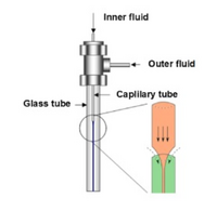
Coaxial devices can compress the central solution in both the vertical and horizontal planes, allowing more defined, three-dimensional focusing. Common devices comprise of concentric capillary tubes, with the inner tube housing the central flow of desired test mixture, and the outer housing the inert sheath fluid (Figure 8). The dimensions of the tubes can be adjusted, along with flow conditions, to determine the flow pattern. The ability of this technique to create tightly defined flow has value in the development of nanoparticles [1].
Planar On-Chip Devices
Planar devices are simple to make, and can be easily included in experiments. They lack the vertical compression of coaxial tubes, leaving most with only two-dimensional (2D) focusing. 2D focusing creates a sheet of the fluid of interest between the planes of sheath fluid. These 2D devices are produced using soft lithography and are low cost (Figure 9). They are easy to make, even with complex designs, and can be integrated easily into larger on-chip designs. Hydrodynamic focusing is induced on the central solution by introducing sheath flows on either side of the central flow, compressing it in the horizontal plane [1]. The central flow can be “decentralized” or manipulated by inducing asymmetric focusing. Asymmetric focusing uses sheath flows with different flow rates to adjust the position of the central flow [5]. Bifurification can be used to separate the products from the inert sheath fluid.
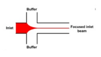
3D focusing on a chip is possible, but more challenging. These designs require multiple layers on-chip. This would allow sheath flow to squeeze the central flow not only from the side, like in the 2D model, but from the top and bottom as well. This is more complicated, more difficult to make, and more expensive to produce. To achieve 3D focusing on a single layer planar chip, multiple inlets must be used to introduce the sheath fluid [1].
Microfluidic Drifting
Microfluidic drifting can be used to induce hydrodynamic focusing by implementing a curved microfluidic channel on the device. Microfluidic drifting is when the flow of the fluid of interest experiences drift in the lateral direction. This drift is caused by the curve of the channel, which causes a centrifugal effect and influences secondary flow within the fluids. The extent of the microfluidic drift depends on the flow rate of the sheath fluid and the flow rate of the fluid of interest. For three-dimensional hydrodynamic focusing the fluid of interest can be flattened into a vertical sheet using the microfluidic drifting method and then compressed in the horizontal direction using traditional methods of introducing streams of sheath fluid [7].
Applications
The major applications of hydrodynamic focusing are flow cytometry and fast mixing.
Flow Cytometry
Cytometry is the counting of cells in a solution. It is very important to the study of life sciences involving biological components. Hydrodynamic focusing allows for accurate cell population sizing [6]. Controlling the width of the central flow is crucial to cell characterization procedures, because it must match the size of the cell of the measurements will be inaccurate [5]. The downside to cytometry with 2D focusing is the inability to produce uniform velocity which can result in undetected particles. Additional details on this technique can be found [| here].
Fast Mixing
Laminar mixing is an asset that draws researchers to the microfluidic scale. Mixing that is otherwise impossible or dangerous to the sample can be completed in the microscale because mixing can occur quickly without having to introduce turbulence. This ability is brought to the next level using hydrodynamic focusing. In already small channels (on the order of 10 um), hydrodynamic focusing allows streams of the fluid of interest to reach sizes in the order on nanometers. Molecules introduced through side flow can diffuse into the stream easily at this scale and mixing occurs quickly and without turbulence. Devices utilizing this can be made using standard photolithography [9]. One particular example of this is the study of protein folding [8].
Protein Folding
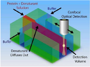
One of the biggest applications of hydrodynamic focusing for passive mixing is protein folding. There has been a lot of research done on the kinetics of protein folding but mixing times have limited research done on proteins with folding times with less than 10 microseconds. The folding time of proteins may vary from nanoseconds to seconds or even longer. When studying the kinetics of protein folding, hydrodynamic focusing may be used. Hydrodynamic dynamic focusing uses laminar flow with small mixing times as opposed to turbulent flow which would have small mixing times but does not allow precise numeric simulations [10]. As seen in Figure 10, a solution of protein and denaturant is flown in the middle as the focused stream and buffer is flown in the sides as the focusing streams. Due to the small size of the denaturants, they diffuse out much faster than the proteins allowing the proteins to fold. Waldauer et al. was able to diffuse denaturant ~100 fold in ~8 microseconds [11]. For more details, view the page on Microfluidics for Studying Protein Folding Diseases.
References
[1] Lu, M.; Ozcelik, A.; Grigsby, C.; Zhao, Y.; Guo, F.; Leong, K.; Huang, T. Microfluidic Hydrodynamic Focusing For Synthesis Of Nanomaterials. Nano Today 2016, 11, 778-792. https://www.sciencedirect.com/science/article/pii/S1748013216302511
[2] Hessel, V., Löwe, H., & Schönfeld, F. (2005). Micromixers—a review on passive and active mixing principles. Chemical Engineering Science, 60(8), 2479–2501. https://doi.org/10.1016/j.ces.2004.11.033
[3] Knight, J.B.; Vishwanath, A., Brody, J., & Austin, R. (1998). Hydrodynamic Focusing on a Silicon Chip: Mixing Nanoliters in Microseconds. Physical Review Letters - PHYS REV LETT, 80, 3863–3866. https://doi.org/10.1103/PhysRevLett.80.3863
[4] Veenstra, T. T., Lammerink, T. S. J., Elwenspoek, M. C., & Berg, A. van den. (1999). Characterization method for a new diffusion mixer applicable in micro flow injection analysis systems. Journal of Micromechanics and Microengineering, 9(2), 199. https://doi.org/10.1088/0960-1317/9/2/323
[5] Lee, G.; Chang, C.; Huang, S.; Yang, R. The Hydrodynamic Focusing Effect Inside Rectangular Microchannels. Journal of Micromechanics and Microengineering 2006, 16, 1024-1032. https://iopscience.iop.org/article/10.1088/0960-1317/16/5/020/pdf
[6] Shuler ML, Aris R, Tsuchiya HM. Hydrodynamic focusing and electronic cell-sizing techniques. Appl Microbiol. 1972;24(3):384-8. https://www.ncbi.nlm.nih.gov/pmc/articles/PMC376528/?page=1
[7] Mao, X.; Waldeisen, J.; Huang, T. “Microfluidic Drifting”—Implementing Three-Dimensional Hydrodynamic Focusing With A Single-Layer Planar Microfluidic Device. Lab on a Chip2007, 7, 1260. https://pubs.rsc.org/en/content/articlehtml/2007/lc/b711155j
[8] Ivorra, B., Ferrández, M.R., Crespo, M. et al. J.Math.Industry (2018) 8: 4. https://link.springer.com/article/10.1186/s13362-018-0046-3
[9] Knight, J.; Vishwanath, A.; Brody, J.; Austin, R. Hydrodynamic Focusing On A Silicon Chip: Mixing Nanoliters In Microseconds. Physical Review Letters 1998, 80, 3863-3866. https://journals.aps.org/prl/pdf/10.1103/PhysRevLett.80.3863
[10] Lee, G.-B., Chang, C.-C., Huang, S.-B., & Yang, R.-J. (2006). The hydrodynamic focusing effect inside rectangular microchannels. Journal of Micromechanics and Microengineering, 16(5), 1024. https://doi.org/10.1088/0960-1317/16/5/020
[11] A Waldauer, S., Wu, L., Yao, S., Bakajin, O., & Lapidus, L. (2012). Microfluidic Mixers for Studying Protein Folding. Journal of Visualized Experiments : JoVE. https://doi.org/10.3791/3976

