Acoustic Micro-Mixing - Caleb Boucher
Surface Acoustic Waves


Acoustic Micro Mixing (AMM) consist of techniques wherein sound waves increase the rate of diffusive mixing through chaotic agitation of a laminar flow or stagnant well within a microfluidic device1. Video 1 shows haw sound directly applied to a fluid medium can have a significant effect on the surface activity of said medium and with great variety with changing frequency.
AMM makes use of sound waves propagating on some relevant surface as a surface acoustic wave (SAW) to achieve chaotic convection in what would otherwise be a diffusion dominated laminar flow regime1. Surface acoustic waves are sound wave vibrations propagating on the surface of some elastic medium. They are specified as being 'surface' acoustic waves because the transfer of wave energy into and below the surface of the elastic medium is marked with an exponential decay in wave potential, meaning a SAW can only penetrate the elastic medium to a depth comparable with the amplitude of a single wavelength2. A good example of a surface acoustic wave is the Rayleigh wave which is characteristic of a SAW propagating on a solid elastic surface as can be seen in the model in Figure 13.
In lab, SAWs can be generated by Inter-digital Transducers (IDT) on piezoelectric crystal substrates as seen in Figure 2. The frequency of the generated SAW [math]\displaystyle{ f = c_{SAW}/2d }[/math]. [Equation 1] Here [math]\displaystyle{ c_{SAW} }[/math] is substrate acoustic velocity and [math]\displaystyle{ d }[/math] is electrode distancing4.
Piezoelectric Material
In SAW generation, high frequency electrical impulse in the IDT causes a physical deformation of the surface due to inverse action of the piezoelectric substrate demonstrated in Video 2. The piezoelectric effect is the reversible action of electrical waves imposing mechanical strain on a solid material or vice versa. By this direct relation between electric impulse and material deformation, the frequency of SAWs produced by IDT are easily controlled vie electric impulsing to through the transducers electrodes.
Acoustic Micro Mixing Designs
In AMM design, the surface that SAWs propagate on is important. Liquids consisting mainly of water are in-compressible and will force deformation to the space surrounding when propagating a SAW. If the fluid being mixed is completely filling an encapsulated well or channel then the energy and time required to perform effective mixing will increase as the waves will be rested on either side of its surface-surface interface by an incompressible fluid and a rigid boundary. For this, an interface between two fluid phases, one being the in-compressible liquid phase to be mixed, and some compressible gas phase which can express acoustic wave vibrations more freely is desirable. There are multiple techniques of varying sophistication to confront this problem through both active measures, and passive design.
-
Figure 3. Basic AMM design using common lab consumables and conventional speakers.5 -
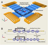
Figure 4. Schematic of a acoustic mixing device via surrounding IDT's. -
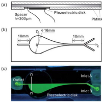
Figure 5. Diagram and image of a mixing space placed over piezoelectric disk.6 -
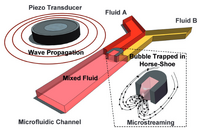
Figure 6. Schematic of a working active bubble mixer with transducer for generated SAW, horseshoe channel design to produce bubble from flow surface tension, and recirculating flow pattern produced by active bubble mixer.8


AMM applications


Open Design
In instances where fluids are mixed within an open well, being exposed to the atmosphere, active mixing can easily be achieved by two or more SAW generators placed around the well. Figures 3 and 4 illustrate such designs where two or more acoustic devices create chaotic convection in a stagnant fluid. The first is a quick inexpensive method where two speakers are taped to the bottom of an acrylic plate with a well being created by tape plastered onto one side of a drilled hole5. Such a device while quick and easy however might have some restrictions on usability and more compact devices may be produced using IDTs4 as in the latter Figure 4.
The mixing regimes in Figure 6 express how acoustic mixing in a well compares with regular diffusion and conventional vortex mixing over a same time interval. Here series A represents stagnant diffusive mixing, series B represents conventional stirring with a vortex, series C makes use of AMM, and series D uses both AMM and some time with a vortex stirrer. The data when analysed showed that AMM is relatively equal to the vortex stirrer in time scale meaning that it could be used as an alternative should mixing be required in a device that might benefit in avoiding a total system agitation such as aggressive shaking by a vortex machine5.
Closed Systems
Bubble Induction in Enclosed Wells
If the fluid is enclosed, due to necessity of fluid flow into and out of the well or other, a gas phase can still be incorporated into the system via bubble induction.6 The working concept involves steep pressure gradients generated by an IDT to force minute levels of vaporization in the mixing space. This can be achieved by SAWs being actuated at resonance frequency to the solution being mixed. Figure 5 shows how such a design is created with a single IDT being placed directly under the enclosed mixing well. When the SAW is produced with changing frequency the actuating frequency can be determined when the laminar flow through the mixing space begins to homogenize as was shown in experimental data in Figure 7. Said experiments can be reproduced with many different fluids and flow-rates and is a highly useful technique in continuous flow microchip experiments. Additionally if a fluid is being used that is difficult to actuate through some material or design restrictions of the chip, bubble induced actuation can still be achieved through the addition of an immiscible phase with a high boiling point such as perflurocarbon, which can be targeted as the vaporizing phase and create the bubble induction required for effective agitation7.
Bubble Addition in Channels
In some cases with microfluidics, near instantaneous mixing of a solution must be achieved. This is a difficult task to achieve in cross sectional channels where fluid flow is laminar and mixing only occurs over a diffusive boundary. SAW application can mix laminar channels, but the degree of mixing is slow and measured across a length of the channel. Here a stationary bubble can be used to achieve near instantaneous mixing of laminar flows across the cross sectional area of the channel as shown in Figure 4.
The bubble mixer makes use of acoustic streaming; a phenomena where acoustic energy is focused on a bubble membrane, emitting concentrated pressure waves into the surrounding media. If the bubble is energized by a SAW set to the resonance frequency of the bubble, calculated in Equation 2, the surface of the bubble will vibrate aggressively and create a local recirculating flow pattern8. This design used the same principle of compressible fluid as in the bubble inducer, but makes use of a single larger bubble incorporated into the design of a channel.
An active bubble mixer can be created with a horseshoe shape as in Figure 3, but can also be applied wherever a bubble can be formed such as in grooves cut into the walls of a channel or in the ceiling of a well if air can be trapped in the system. Actuation of said bubble can be calculated through the Rayleigh-Plesset Equation shown in Equation 2, and the mixing regime of a horseshoe design bubble mixer is shown in Figure 8.
Conclusion
SAWs show promise as a potential active mixing technique as it can be applied over both closed channels and open designs. surface fluid agitation is especially effective at control as mixing speed can be altered both by the fluid flow velocity or IDT design and signaling, both of which are often simple to control.
Acoustic technology is highly developed in the modern world and obtaining low cost sound technology is relatively easy. One of the beautiful aspects of active acoustic mixing technologies it the relative ease all parts for a functional mixer can be obtained. While sophisticated designs can be developed, it does not require much specialized equipment to make a rough apparatus for basic testing8.
References
[1] Ward, K.; Fan, H. Z. Journal of Micromechanics and Microengineering 2015, 25 (9).
http://dx.doi.org/10.1088/0960-1317/25/9/094001
[2] ac692@cam.ac.uk. Surface Acoustic Waves (SAWs).
[1]
[3] Jisis. http://www.av.it.pt/jisis/saw.html
[4] Frommelt, T.; Kostur, M.; Wenzel-Schäfer, M.; Talkner, P.; Hänggi, P.; Wixforth, A. Physical Review Letters 2008, 100 (3).
http://dx.doi.org/10.1103/physrevlett.100.034502
[5] Petkovic-Duran, K.; Manasseh, R.; Zhu, Y.; Ooi, A. BioTechniques 2009, 47 (4), 827–834.
http://dx.doi.org/10.2144/000113242
[6] Wang, S.; Huang, X.; Yang, C. Lab on a Chip 2011, 11 (12), 2081.
http://dx.doi.org/10.1039/c0lc00695e
[7] Bezagu, M.; Arseniyadis, S.; Cossy, J.; Couture, O.; Tanter, M.; Monti, F.; Tabeling, P. Lab on a Chip 2015, 15 (9), 2025–2029.
http://dx.doi.org/10.1039/c5lc00247h
[8] Ahmed, D.; Mao, X.; Shi, J.; Juluri, B. K.; Huang, T. J. Lab on a Chip 2009, 9 (18), 2738.
http://dx.doi.org/10.1039/b903687c
