Reynolds Number (Re) - Blayne Sarazin
Summary

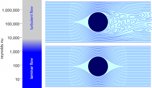
The Reynolds number is a dimensionless quantity in fluid mechanics that is used to help predict flow patterns in different fluid flow situations. The Reynolds Number serves as a guide to the laminar-turbulent transition in a particular flow situation,[1] and for the scaling of similar but different-sized flow situations. The Reynolds number is often used to predict the velocity at which a certain fluid flow turns turbulent, while it can also be used to determine what state of flow the fluid in question is currently under. Calculation of the Reynolds number depends heavily on what type of fluid is being utilized, as well as through what type of channel (i.e. pipe flow, duct, open channel, etc.) this fluid is travelling. Figure 1 is a good example of a fluid experiencing all three types of flows: laminar at the bottom, transitional near the middle of the stream (if only very briefly), and turbulent flow towards the top.
The concept was first introduced in 1851 by George Gabriel Stokes,[2] however it was named by Arnold Sommerfield in 1908[3] after Osborne Reynolds, who popularized its use in 1883.[4]
Definition
The Reynolds Number is defined as the ratio of inertial forces to viscous forces in a flowing fluid. It is used in many fluid flow correlations and is used to describe the boundaries of fluid flow regimes (laminar, transitional and turbulent).[1] Viscous force is what tends to keep the layers moving smoothly. When these forces are sufficiently high, this removes any disturbances from the flow and we see what we call laminar flow. However, as velocity increases, inertia forces increase and particles are pushed out of the smoother path. This causes disturbances within the flow, and will eventually lead to what we call turbulent flow.[5] Determining whether a flow is experiencing laminar or turbulent flow is quite simple. Reynold's number tells us everything we need to know about the behavior of a given flow scenario.
Reynolds number is determined via the following equation:
- [math]\displaystyle{ \mathrm{Re} = \frac{\rho v L}{\mu} }[/math]
where,
- [math]\displaystyle{ \rho }[/math] is the density of the fluid (SI Units: kg/m^3)
- v is the velocity of the fluid (SI Units: m/s)
- L is the characteristic length of the fluid. This varies depending on through what the fluid is flowing (SI Units: m)
- [math]\displaystyle{ \mu }[/math] is the dynamic viscosity of the fluid (SI Units: Ns/m2)
You will sometimes see Reynolds number in a simplified version such as this:
- [math]\displaystyle{ \mathrm{Re} = \frac{v L}{\nu} }[/math]
where [math]\displaystyle{ \nu }[/math] is simply the kinematic viscosity of the acting fluid (SI Units: m2/s). ([math]\displaystyle{ \nu = \mu/\rho) }[/math]
The Reynolds Number can be used to determine if flow is laminar, transient or turbulent.[8] The flow is
- laminar - when Re < 2300
- transient - when 2300 < Re < 4000
- turbulent - when Re > 4000
Flow Types
Reynolds number can tell us the behavior of the flow we are analyzing. Each flow phase corresponds with a specific range of Reynolds numbers. The flow types can be broken down into the following three branches:
Laminar
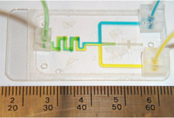
Laminar flow is the flow that corresponds with low velocities and Reynolds numbers less than 2300.[7] In this type of flow, the fluid flows in parallel layers, with no disruption between the layers.[7] At low enough velocities, the fluid will tend to flow without lateral mixing, while adjacent layers simply slide past one another. This can be especially important in microfluidics when you do not want lateral mixing. These phenomenon are displayed well by the streamlines depicted in the laminar flow case of Figure 2. Note that the flow is very clean and without disturbance. Furthermore, laminar flow is entirely reversible.[9] This means that we can always return to almost exactly where we began when the flow started.

Transitional (transient)
Transitional or transient flow is the phase of flow that occurs between laminar and turbulent flow, and corresponds to Reynolds numbers that land between 2300 and 4000[7]. In this type of flow, there is a mixture of laminar and turbulent flows present. As Reynolds number increase from 2300 to ~4000, there are an increasing amount of disturbances appearing within the flow.
Turbulent
Turbulent flow is the most common form of flow in nature, and corresponds to the Reynolds numbers higher than a value of 4000[7]. Turbulent flow is ultimately described as chaotic and unpredictable, and is often seen with fluids at high velocities. The flow undergoes irregular fluctuations, or mixing, and continuously changes magnitude and direction.[11] As can be seen from Figure 2, the sphere in the upper portion of the figure has steady streamlines in front of it, but severe eddy (vortex) formation behind it. Since turbulent flow is extremely hard to measure compared to laminar flow, experimental tools such as a hot wire probe[12] must be used in order to obtain good results. A hot wire probe is a device that has a very fast response time, with a probe that can respond to temperature changes within 1 millisecond, which makes this tool a good candidate for measuring flows (such as air) that experience constant, rapid change as we see in turbulent flow.
Flow Scenarios
Calculation of the Reynolds number for a given fluid depends on several things such as speed, density, and viscosity. Two of these are properties of the fluid itself and are usually pretty easy to look up. Speed is often a given, or is one of the things you are trying to solve for if initially given a Reynolds number. However, the characteristic length is something that changes based upon what the fluid is flowing through. The following sections will describe how calculation of characteristic length changes, and will show the equations to use in each of these situations.
Pipe Flow
Let's say you have water flowing through a pipe with a diameter of 25 millimeters at a speed of 5 meters per second. If we take a look at the equation for Reynolds number defined above, we simply need to replace to the characteristic length term with a D, which denotes the diameter of the pipe. The equation then looks as such:
[math]\displaystyle{ \mathrm{Re} = \frac{\rho v D}{\mu} }[/math]
- where D is the diameter of the pipe (SI units: m)
For this specific scenario, the equation with the aforementioned values plugged in becomes:
[math]\displaystyle{ \mathrm{Re} = \frac{(1000kg/m^3)(5 m/s)(0.025 m)}{1.002 Ns/m^2} = 124.75 }[/math]
This is laminar flow based on the previously defined boundaries. To create turbulent flow, the velocity or diameter of the pipe would have to be increased. Increasing either would easily force the flow to approach turbulence.
Duct
You can imagine a duct as either a square or rectangular structure through which the fluid is flowing. For this, the calculation of Reynolds number changes slightly due to the fact that we use something called the hydraulic diameter is the characteristic length.[7] The hydraulic diameter, [math]\displaystyle{ D_h }[/math], is defined by the following equation[7]:
[math]\displaystyle{ \mathrm{D_h} = \frac{4A}{U} }[/math]
where,
- [math]\displaystyle{ D_h }[/math] is the hydraulic diameter of the duct.
- A is the area of the duct.
- U is the wetted perimeter of the duct.
While the U term may be somewhat confusing because it is not simply just perimeter, wetted perimeter just means the cross-sectional perimeter that is in contact with the acting fluid. For a square, this U term becomes [math]\displaystyle{ 2*(a+b) }[/math]
So the [math]\displaystyle{ D_h }[/math] term turns into [math]\displaystyle{ \mathrm{D_h} = \frac{4*(a*b)}{2*(a+b)} }[/math] which simplifies into the following equation we use to calculate the hydraulic diameter:
[math]\displaystyle{ \mathrm{D_h} = \frac{2*(a*b)}{a+b} }[/math]
Therefore, our original equation for Reynold's number takes the following form when were are dealing with a rectangular duct:
[math]\displaystyle{ \mathrm{Re} = \frac{\rho v D_h}{\mu} }[/math]
Open Channel
An open channel or duct behaves similarly to the previously mentioned closed duct. The only thing that changes in this case is the wetted perimeter. The following problem explores the small difference between open and closed ducts:

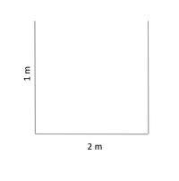
The perfect example of an open duct that transports a fluid is an aqueduct, which was used to transport water for various reasons. Imagine we have an aqueduct with the dimensions shown in Figure 3 and we want to calculate the Reynold's number for water flowing at 25 meters per second.
The hydraulic diameter for this case is simply:
[math]\displaystyle{ \mathrm{D_h} = \frac{4*(2*1)}{2+1+1} = 2 }[/math]
- Note that the wetted perimeter for an open channel differs slightly because there are only three walls used when calculating the hydraulic diameter. This is the only difference between open and closed ducts.
[math]\displaystyle{ \mathrm{Re} = \frac{(1000kg/m^3)(25 m/s)(2 m)}{1.002 Ns/m^2} = ~ 49900 }[/math]
Therefore, the flow within this duct is fully-developed turbulent flow.
Reynolds Number in Microscopic Flow

As far as Reynold's number and microfluidics is concerned, flow is almost always laminar. Meaning that almost without exception, microfluidics experience extremely small Reynolds numbers. The reasons the Reynolds numbers are kept so low is a result of low velocities and small channel sizes. Typical velocities range from 1 micrometer per second up to 1 centimeter per second, while channel radii ranges from 1-100 micrometers.[13] Constrained by these dimensions, the Reynolds number lands safely within the laminar regime, the viscous forces almost always dominate over the inertial forces, resulting in smooth, laminar flow.
Hemodynamics

Hemodynamics is a word specifically used to address blood flow within the human body.[15] When considering how Reynolds number works in the body, we must first address a few important things about flow within the body. When dealing with the circulatory system, the following key differences must be addressed:[15]
- Blood is a non-Newtonian fluid, meaning that blood viscosity is not constant.
- Flow in the body is pulsatile. In this case, the flow moves forward in pulses. Furthermore, between the pulses the flow actually reverses direction for a very short period of time.
- Blood vessels are elastic "pipes" whose shapes and diameters constantly change.
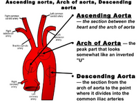
Calculating Reynolds number can only be done locally, and is not representative of the flow everywhere in the body at that time. For this application, one would treat arteries like pipes. Further measurements may be necessary to attain flow velocity. With that being said, blood flow in the body is generally laminar, with the exception usually occurring in the ascending aorta where this flow can be disrupted and turn turbulent.[16] The location of the ascending aorta can be seen in Figure 5. This turbulent flow can also occur in large arteries at branch points as well as across stenotic heart valves. Ideally, the critical Reynolds number is high enough such that turbulent flow is not common in the circulatory system. Turbulent blood flow within the circulatory system is never a good thing, with turbulent flow being linked to heart murmurs[16] and aneurysm formation at arterial branch points.[17]
References
1. Neutrium Reynolds Number. https://neutrium.net/fluid-flow/reynolds-number/ (accessed Feb 26, 2022).
2. Stokes, G. G. On the Effect of the Internal Friction of Fluids on the Motion of Pendulums. Mathematical and Physical Papers 1–10. DOI 10.1017/cbo9780511702266.002
3. Sommerfeld, A. Ein Beitrag Zur Hydrodynamischen Erkläerung Der Turbulenten Flüssigkeitsbewegüngen (A Contribution to Hydrodynamic Explanation of Turbulent Fluid Motions). International Congress of Mathematicians 1908, 3, 116–124. https://www.mathunion.org/fileadmin/ICM/Proceedings/ICM1908.3/ICM1908.3.ocr.pdf
4. Reynolds, O. XXIX. an Experimental Investigation of the Circumstances Which Determine Whether the Motion of Water Shall Be Direct or Sinuous, and of the Law of Resistance in Parallel Channels. Philosophical Transactions of the Royal Society of London 1883, 174, 935–982. DOI 10.1098/rstl.1883.0029
5. Significance of Reynolds number in pipe flow. https://www.uobabylon.edu.iq/eprints/paper_2_2117_1369.pdf (accessed Feb 27, 2022).
6. Reynolds number. https://en.wikipedia.org/wiki/Reynolds_number (accessed Feb 27, 2022).
7. The Engineering ToolBox Reynolds Number. http://www.engineeringtoolbox.com/reynolds-number-d_237.html (accessed Feb 27, 2022).
8. Batchelor, G. K. An Introduction to Fluid Dynamics. Cambridge University Press, 2012. DOI 10.1017/cbo9780511800955
9. Laminar flow. https://youtu.be/p08_KlTKP50 (accessed Feb 27, 2022).
10. Laminar flow - viscous flow: Definition & characteristics. http://www.nuclear-power.net/nuclear-engineering/fluid-dynamics/laminar-flow-viscous/ (accessed Feb 27, 2022).
11. Turbulent Flow http://abyss.uoregon.edu/~js/glossary/turbulent_flow.html (accessed Feb 27, 2022).
12. web.mst.edu - /cottrell/ME240/Resources/. Fluid flow instrumentation - missouri S&T. https://web.mst.edu/~cottrell/ME240/Resources/Fluid_Flow/Fluid_flow.pdf (accessed Feb 27, 2022).
13. Squires T. M.; Quake S. R. Microfluidics: Fluid Physics at the Nanoliter Scale. Reviews of Modern Physics 2005, 77 (3), 977–1026. DOI 10.1103/revmodphys.77.977
14. MNSA Lab. Laminar flow in microfluidic channels. Department of Electrical and Computer Engineering,
University of Wisconsin-Madison, USA
. https://mnsa.ece.wisc.edu/Outreach/Expo2007/EXPO2007.pdf (accessed Feb 27, 2022).
15. Bioengineering/Physiology 6000: System Physiology I: Cardiovascular, Respiratory, and Renal Systems. Hemodynamics. University of Utah. https://www.sci.utah.edu/~macleod/bioen/be6000/notes/L09-hemo.pdf (accessed Feb 27, 2022).
16. Cardiovascular Physiology Concepts Turbulent flow. https://www.cvphysiology.com/Hemodynamics/H007 (accessed Feb 27, 2022).
17. Foutrakis G.; Yonas H.;Sclabassi R. Saccular Aneurysm Formation in Curved and Bifurcating Arteries. American Journal of Neuroradiology 1999, 7, 1309–1317. PMCID: 10472991
