The Paper that Launched Microfluidics - Xi Ning
Introduction
Microfluidics is the science and technology of systems that process or manipulate small (10 −9 to 10 −18 litres) amounts of fluids, using channels with dimensions of tens to hundreds of micrometres, as stated by George Whitesides. [1] Microfluidic devices are microchemical systems such as labs-on-a-chip, organs-on-a-chip and plants-on-a-chip. They leverage several characteristics: 1) laminar flow in microchannels; 2) higher surface area to volume ratio; and 3) higher heat and mass transfer rates. [1][2] Compared to macroscale systems, these devices bring new capabilities to control transport phenomena including quicker analysis time, reduced material consumption and enhanced portability. [1 3] (see also The Benefits of Small Length Scales in Microscale Systems).
Tracing back to the origin of microfluidics, the paper by Harrison et al. [4] is widely recognized for establishing and popularizing microfluidics as a research field, pioneering the phrase “laboratory-on-a-chip” and showing its feasibility. [5] It successfully showcased the development of an integrated, miniaturized double-glass chemical analysis system that included sample injection, treatment, and detection, achieving accurate quantification and rapid, precise separation of amino acids. [4]
Significance
The 1993 Science paper by Harrison et al. was revolutionary because it demonstrated how to create a high-quality, integrated miniaturized chemical analysis system using the alternative technologies: electroosmotic pump and capillary electrophoresis. [4] In the 1990 paper by Manz et al., the concept of miniaturized total chemical analysis systems (μTAS) was proposed as an alternative to the existing analysis systems and chemical sensors, offering improved performances [6] In 1992, Manz et al. conducted the first capillary electrophoresis experiment on the chip-like structure crafted through micromachining - a photolithographic technique for microscale structures predominantly utilized in silicon microelectronics back then. [1][3] Micromachining was also limited to developing 3-D sensors and actuators for physical forces, as well as tweezers, beams, pumps, and valves.[4] These microfabricated pumps and valves had limited quality and obstructed the system development.[5] Then, in 1993, Harrison et al. realized the concept of (μTAS) proposed in the 1990 paper through micromachining.[4] Not only including capillary electrophoresis, the system integrated multiple processes to inject, detect and separate amino acids while controlling the flow rate through electroosmotic flow at high efficiency.[4]
The feasibility of the system, demonstrated in the 1993 paper by Harrison et al. sparked particular interests because of its identified advantages such as higher efficiency, less sample consumption and less manufacturing costs. Its potential and usefulness were recognized in various fields. In the 1990s after the cold war, the Defense Advanced Research Projects Agency (DARPA) of the US Department of Defense funded microfluidic devices to detect chemical and biological weapons. [1] Genomics in the field of molecular biology required higher throughput analytical methods that microfluidics can resolve. [1] In 1995 to 2000, companies like Orchid Biosciences Inc., Cepheid, and Caliper Technologies Corp. exploited the dot-com “boom” also known as “bubble” to achieve market values of more than one billion US dollars.[5]
Device Fabrication
In the paper by Harrison et al., standard wet micro-photolithography was used for micromachining.[4] This technique develops a chemical analysis system with two layers of glass. Polished and fine-annealed glass served as the bottom substrate. The etchant was a 1 L solution composed of 200 mL of 49% hydrofluoric acid and 140 mL of 70% nitric acid. The copper and chromium metal mask with dimensions of 10 μm etched capillary channels of 1 to 10 cm long, 10 to 20 μm depth and 30 μm width. The yield was 70% probably due to the defects of the glass being used (Coming 7740 Pyrex). This etching, classified as wet etching, typically produces isotropic channels with curvature, as observed here. The top glass, featuring sufficient holes, was thermally bonded (see more information in Bonding Surfaces to the etched bottom glass by heating it between 650°C to 660°C for 4 to 6 hours one or two times. Plastic pipette tips were inserted into the holes of the top glass, acting as reservoirs for samples, buffer, and platinum electrodes.
Electrokinetic effect
The paper discusses controlling the flow direction and separating amino acids through the electrokinetic effect, which combines electroosmotic flow with capillary electrophoresis.[7]
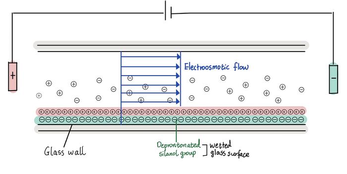
The electroosmotic flow, explained by the electric double layer theory, is the movement of an uncharged liquid over a charged surface under an applied electric field.[8][9] As shown in Figure 1, the uncharged buffer solution or electrolyte is propelled from the anode to the cathode by an electroosmotic pump through applied voltage on the charged silica or glass surface; here, the silanol groups on the glass surface become deprotonated and negatively charged in the buffer solution.[8][9] Instead of moving parabolically as shown in pressure-driven system, fluid moves as a plug, making high separation of ionic species. [1] The rate of electroosmotic flow is controlled by the field strength and the charge density on the capillary wall.[7]
Then, the mixtures of compounds such as amino acids in the paper are separated based on electrophoretic mobility which is inversely related to atomic radius and directly proportional to solvent viscosity and mass to charge ratio.[7] The method is known as the capillary electrophoresis, and the paper uses zone capillary electrophoresis which separates samples into bands or zones with clear boundaries.[7] Finally, detectors such as UV/VIS, mass spectroscopy, and fluorescence can be used to identify different compounds.

Microfluidic set-ups and its efficacy
Separation and quantification
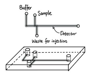
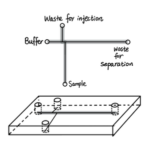
Harrison et al. designed two microfluidic set-ups labeled as set-up, 1 which is capable of separating more amino acids and the miniaturized version called set-up 2 that uses shorter separation distances. These two set-ups’ specific parameters and efficiency summarized in Table 1. The general layouts of two set-ups and the corresponding electropherograms are shown in Figures 2 and 3, respectively. After the mixtures of amino acids were attached with the fluorescence label, FTIC which was then excited, samples were injected through the appliance of the voltage across different reservoirs of the plastic tips of the inset as described in Table 1. Then, separation was facilitated by changing the location of the voltage appliance.
Set-up 1 and 2 both had satisfactory results. Set-up 1 obtained six amino acids from 17 to 32 plates was comparable to the older version of infused silica capillary, while set-up 2 possessed a quick response time of 3 seconds similar to that of chemical sensors.[4] Furthermore, the electropherogram of set-up 1 shows bands with less broadening indicating higher resolution.[4]
Additionally, the system was used for quantifying two amino acids: Arg and Tyr assuming complete reaction with the fluorescence label, FTIC. The calibration curve of the integrated area of the electropherogram showed a linear relationship from 0.05 to 20 μM with precision ± 2 - 4%.[4]


| Parameters | Set-up 1 | Set-up 2 |
|---|---|---|
| Number of amino acid separated | 6 | 3 |
| Injection-detection distance (Separation distance) | 2.2 cm | 0.75 cm |
| Injection locations and voltage | 2 kV (1.2 kV/cm) between waste reservoir for injection and sample in Figure 2 | 500 kV between injection reservoir and sample in Figure 3 |
| Injection time | 10 s | 1 s |
| Separation location and voltage | 11.25 kV (1.06 kV/cm) between waste reservoir for separation and buffer in Figure 2 | 2.5 kV (1.56 kV/cm) between waste for separation and buffer in Figure 3 |
| Voltage across separation | 2.3 kV | 1.17 kV |
| Analysis time | 25 s | 3s |
| Number of theoretical plates obtained | 40, 000- 75, 000 | about 600 |
Sample dilution

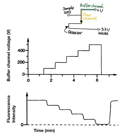
In the paper, Harrison et al. was able to controllably dilute samples for sample preparation through varying the applied potential of the diluent; electroosmotic flow rate is directly proportional to the applied voltage.[4 7] As shown in Figure 4, the “T” shape mixes buffer and the fluorescence-attached amino acid. As the applied potential of the buffer reservoir increases, the electroosmotic flow increases and the amino acid becomes more diluted with decreasing fluorescence intensity. Likewise, the mixing ratio is controlled by the relative voltages of the sample channel to the voltages across the buffer channel.
Leakage from inactive channels
Harrison et al. noticed when the side channel of the set-up 2 of Table 1 (Figure 3) was left uncontrolled, leakage from the inactive side channel into the active channel during separation. [4] In this case, the potential of buffer and waste for separation reservoir was only controlled as specified in Table 1, resulting in 3% to 4% leakage from the inactive sample channel. The leakage was problematic, resulting in up to 20 to 30% increase in background fluorescence signal.[4]
Harrison et al. proposed that the leakage was due to the combination of convective flow and diffusion.[4] When the potential of all reservoirs that intersect the manifold as shown in the “T” shape set up of Figure 4 was controlled, the leakage or overflow from the inactive channel was avoided.
Summary
The paper by Harrison et al. [4] that launched microfluidics successfully developed the miniaturized chemical analysis systems on the glass substrate with electrokinetic effects through micromachining. Since then, the field of microfluidics is growing and more articles are citing the paper (Based on Google scholars, Clarivate's Web of Science: >1500 citations and Clarivate's Web of Science: >2600 citations). [5] The materials now include polydimethylsiloxane (PDMS), thermoplastics, paper, fabrics, etc. Applications extend from healthcare such as point-of-care diagnosis and organ on a chip to detection such as identifying contaminants in food and environment. [5]
References
1. Whitesides, G. The origins and the future of microfluidics. Nature, '2006, 442, 368–373. DOI: https://doi.org/10.1038/nature05058
2. Sun, B.; Jiang, J.; Shi, N.; Xu, W. Application of Microfluidics Technology in Chemical Engineering for Enhanced Safety. Process Saf. Prog., 2015, 35 (4), 365–373. DOI https://doi.org/10.1002/prs.11801.
3. Manz, A. et al. Planar chips technology for miniaturization and integration of separation techniques into monitoring systems — capillary electrophoresis on a chip. J. Chromatog., 1992, 593, 253–258. DOI: https://doi.org/10.1016/0021-9673(92)80293-4
4. Harrison, D.J.; Fluri K.; Seiler K.; Fan Z. H.; Effenhauser C. S.; Manz A. Science, 1993, 261, 895–897. DOI: https://doi.org/10.1126/science.261.5123.895
5. Hugh F. Z.; Harrison D.j. Celebrating the 30th anniversary of a pioneering microfluidics paper.Lab Chip, 2023, 23, 4157. DOI: https://doi.org/10.1039/d3lc90076b
6. Manz, A.; Graber, N.; Widmer H.M. Miniaturized total chemical analysis systems: A novel concept for chemical sensing, Sensors and Actuators B: Chemical, 1990, 1 (1-6), 244-248. DOI: https://doi.org/10.1016/0925-4005(90)80209-I.
7. Shah M.; Patel N.; Tripathi N.; Vyas V.K. Capillary electrophoresis methods for impurity profiling of drugs: A review of the past decade. J Pharm Anal., 2022, 12 (1), 15-28. DOI: https://doi.org/10.1016/j.jpha.2021.06.009.
8. Wang X.; Cheng C.; Wang S.; Liu S. Electroosmotic pumps and their applications in microfluidic systems. Microfluid Nanofluidics, 2009, 6 (2), 145. DOI: https://doi.org/10.1007/s10404-008-0399-9.
9. Chen C.; Santiago, J. G. A planar electroosmotic micropump. Journal of Microelectromechanical Systems, 2002, 11 (6), 672-683. DOI: https://doi.org/10.1109/JMEMS.2002.805055.
