Diffusional Broadening - Nicholas Papianou
Diffusional Broadening
As a result of small channel sizes and dimensions, microfluidic systems are almost always characterized by laminar flow due their exceedingly low Reynolds numbers (Re). Likewise, a system’s Péclet number (Pe), the ratio of convection to diffusion, can be calculated. As a whole, diffusion is the only method of mixing that takes place. Preparing samples ahead of time may reduce the amount of diffusion needed, however it remains unavoidable in natural flow. Diffusional broadening refers to the behavior expressed by two things in contact with each other containing a concentration gradient. After a sufficient amount of time, enough particles will diffuse to form a new distinct region representing the mixing. The longer they remain in contact, the larger the interdiffusional zone becomes, leading to more mixing. Due to the nature of the process, this can take a long time and preceding steps may need to be taken in order ensure efficient mixing. Some examples will be explored below that either prefer or try to limit this effect depending on the application.

Characteristics of the Flow
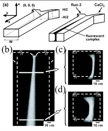
Generally, the Péclet number is the best way of characterizing the flow and mixing within a microfluidic device. This is defined as the ratio of convective transport to diffusive transport. Thus, flow dominated by convection, corresponding to a larger Péclet number with high velocity, will not mix as much as slower moving flow with a smaller Péclet number. When visualizing the flow, a top view image of the yz plane would look similar to the flow shown in Figure 1b while a cross sectional view of the xy plane may look like flow shown in Figure 1c.[1] This view of the xy plane would be equivalent to observing a “slice” in the microfluidic channel and can take the form of an hourglass when the Péclet number is large. In the case of low Péclet number flow, the hourglass would lose its shape and a wide region of mixing would occur due to diffusion dominating. The reason for this flow profile comes from the no-slip boundary condition in fluid mechanics. The local velocity of the fluid is lower near the edge and higher towards the middle.[2]
Due to the relative diffusivities of the two types of flow, the mixing may occur in an asymmetrical manner as shown in Figure 1.[1] In this case, the broadening of the diffusional zone favors one side more than the other since the relative diffusivities are not equal. One will move particles from higher concentration to lower quicker than the other, leading to this asymmetrical pattern. In other words, the more diffusive stream will transport more efficiently than the less diffusive stream. In other instances, the relative diffusivities may be equal to each other, leading to symmetrical broadening. Both streams would transport particles at the same rate, preventing the mixed region from "leaning" in one direction. With proper control of the Péclet number, the two flows can be effectively separated without the need for a physical barrier.
Uses and Applications
Fuel Cells
Society is constantly looking for new ways to power small portable devices without the need for frequent recharging. Currently, designs are making use of proton exchange membranes (PEM) to separate the cathode and the anode ends of fuel cells.[4] However, these tend to perform poorly at large temperatures as the PEM dries out easily. Instead, some researchers are looking to use flow at sufficiently large Péclet numbers to prevent the need for a physical barrier while also limiting the effects of diffusional broadening. Using highly controlled flow, the liquid-liquid interface will not mix appreciably, leaving the two ends of the fuel untouched.[4] This greatly simplifies the fuel cell’s design, but comes with some challenges of its own. Transport of reactants through the boundary layer to the electrodes leads to low amounts of oxidant in the cathode stream. New designs and the use of solvents with high oxygen adsorption ability should improve results.

Blood Diagnostics
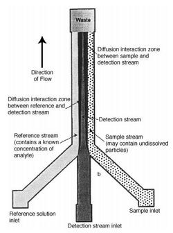
Another application of diffusional broadening is to assist the detection and monitoring of small proteins or ions in blood.[5] Blood cells are large and will not have enough time to diffuse, while small proteins and ions have much larger diffusion coefficients. Thus, these differences in diffusivities can be used to filter the proteins from the blood. The process can be thought of like an H-filter which is commonly used to separate particles by size. Instead, in this case, the detection was achieved by utilizing three different inlet streams in a T-Sensor. An in-depth diagram is shown in Figure 2.[5] A reference enters on the left, an indicator in the middle, and a sample on the right. Upon entering the system, the small molecules will begin diffusing towards the middle indicator stream. As the particles and fluorescent indicators interact, they will become optically visible. Concentrations can be determined based on the comparisons between the sample and reference streams fluorescence. This allows control and compensation for uncertainties that may arise, such as varying light source stability, flow geometry, turbidity and other fluid parameters.
Plug Flow
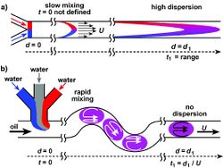
Diffusional broadening does not just occur when flow occurs in a side-by-side basis. It can also be present when looking at plug flow. Generally, it behaves in a manner that can be characterized by Taylor dispersion. Shown below in Figure 3 is this kind of mixing.[6] This may or may not be desired depending on the application. In the case of chromatographic analysis, this is undesired. Techniques such as Isotachopherisis are being studied and implemented to prevent such mixing from occurring in plug flow. By taking advantage of the differential mobility of buffers, the electric fields generated by electrolytic solutions can limit diffusion.

Bibliography
[1] Ismagilov, R. F., A. D. Stroock, P. J. A. Kenis, G. Whitesides, and H. A. Stone, 2000, Appl. Phys. Lett. 76, 2376. https://doi.org/10.1063/1.126351
[2] Brody, J. P., Yager, P., Goldstein, R. E., & Austin, R. H. (1996). Biotechnology at low Reynolds numbers. Biophysical Journal, 71(6), 3430-3441. https://doi.org/10.1016/S0006-3495(96)79538-3
[3] Squires, Todd & Quake, Stephen. (2005). Microfluidics: Fluid physics at the nanoliter scale. Reviews of Modern Physics. 77. https://doi.org/10.1103/RevModPhys.77.977
[4] Choban, Eric & Markoski, Larry & Wieckowski, Andrzej & Kenis, Paul. (2004). Microfluidic fuel cell based on laminar flow. Journal of Power Sources. 128. 54-60. https://doi.org/10.1016/j.jpowsour.2003.11.052
[5] Weigl, B., Kriebel, J., Mayes, K. et al. Whole Blood Diagnostics in Standard Gravity and Microgravity by Use of Microfluidic Structures (T-Sensors). Mikrochim Acta 131, 75–83 (1999). https://doi.org/10.1007/s006040050011
[6] Song, H., Tice, J.D. and Ismagilov, R.F. (2003), A Microfluidic System for Controlling Reaction Networks in Time. Angewandte Chemie International Edition, 42: 768-772. https://doi.org/10.1002/anie.200390203
