Stokes Trap- William McInerney
Background of Particle-Trapping
It is desirable to have direct control over the positioning of particles and other structures in order to study particle interactions or the assembly of materials. There are several methods in which this can be accomplished. For instance, optical traps can be used where laser beams form a gradient force trap known as “optical tweezers” that can manipulate dielectric particles [1]. This technology has been built upon over the years and has proven to be transformative for the fields of physics and biology. For instance, in one study a team combined the technologies from optical tweezers and dielectrophoresis to allow for the manipulation of cells and micron-scale particles [2]. Other traps that are in use consist of magnetic trapping, acoustic traps, electrokinetic traps, and lastly hydrodynamic traps. These traps can vary depending on whether they are passive or active. Optical traps for instance often do not use a control strategy for particle manipulation and are passive [3]. Many of the other strategies used for particle-trapping do utilize control-based confinement. A control design becomes important in electrokinetic and hydrodynamic traps where disturbances can often affect the manipulation efficiency.
Hydrodynamic Trapping
Many of the particle-trapping techniques are constrained based on the particle and medium properties. For example, the optical properties of the particle must be considered when manipulating with optical tweezers. Hydrodynamic traps, on the other hand, use fluid flow to manipulate the particles and the physical and chemical properties do not affect the performance of the trapping. These devices can trap particles ranging from large vesicles to small nanoparticles [3]. The first hydrodynamic trap came about in 1934, when a researcher used four continuously rolling cylinders to form a stagnation point flow [4]. This process required manual input from the user to control the process. As time went on automated controls were put in place and more advanced hardware was used to obtain different flow regimes. The Schroeder lab at the University of Illinois at Urbana-Champaign, have been at the forefront in this area of research. For instance, the Schroeder lab constructed a hydrodynamic trap that confined a particle to a desired location [5]. This device consists of multiple valves where flows were controlled by a PID controller.

Stokes Trap
Stokes flow regimes can be found in low Reynolds flows (Re <<1) where the viscous properties of the fluid dominate [6]. Once a hydrodynamic trap exhibits sufficiently low Reynolds flow, then it can become a Stokes trap. This process was first established in a landmark study published by Shenoy et al. out of the Schroeder lab [3].
Device Construction
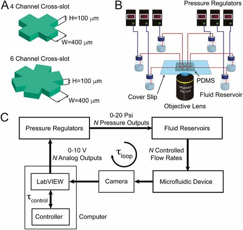
It is desirable to control multiple particles at once. In the study conducted by Shenoy et al., devices were made to control a single particle as well as two particles simultaneously [3]. The number of fluid channels must be greater than or equal to 2P +1 (where P is the number of particles). Otherwise the system will not be clearly defined and will not work properly. For this reason, a device with 4 channels was constructed for single particle manipulation and 6-channel device was used for manipulating 2 particles [3]. The PDMS device as shown in Figure 2 was constructed. It uses controlled pressure regulators to adjust the flows so that the particles can be manipulated.

Control Strategy
The control equations are defined by the net mass flux in the slit equating to zero and using a Hele-Shaw flow model [3]. The Stokes trap uses model predictive control in order to position the particles in the proper location. A high-level control strategy is desired in order to allow the particle to be manipulated precisely even with inaccuracies in the model equations and instrumentation. The models are optimized and the scalar weight in the objective function are dynamically tuned in order for the particle to reach its target location.
Applications
Particle Manipulation and Assembly
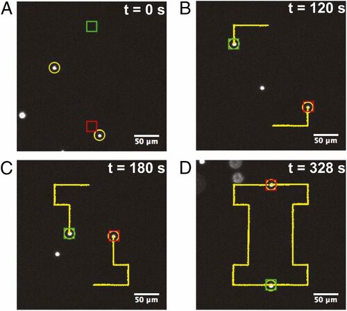
A Stokes trap allows for accurate positioning of particles to a target position. Micron-sized fluorescent beads were manipulated in the device with the model predictive control. The control algorithm was shown to be robust as the device had minimal fluctuation from its path to the target location. Additionally, two particles were manipulated simultaneously in the 6-channel device. The particles successfully interchanged their positions in a relatively brief amount of time. Additionally as shown in Figure 3, a pre-programmed path was used to allow the synchronized particles to draw out an “I” while they interchanged their position. There have been other Stokes trap designs that use optically activated micro-rotors as well to trap particles efficiently [7]

One of the most appealing aspects of a Stokes trap is using it for a controlled assembly of particles. This could have applications in areas such as studying the interactions in vesicle surface membranes, coacervate droplet interactions, interactions between cells, and many other areas of research [3]. In the device made by Shenoy et al., it was found that particles could be directly linked together [3]. The research team allowed the two particles to get with in range of each other so that a biotin-streptavidin interaction formed and allowed the particles to assemble.
Hydrodynamic Trapping in Combination with Other Methods
Hydrodynamic control can be used in combination with other technologies for effective trapping. For example, researchers have used hydrodynamic forces in combination with curvature-induced capillary quadrupolar interactions to manipulate nanosheets to a precise location [8]. Nanosheets have been known to be challenging to position accurately and repeatably given that they are long and thin. In order to overcome this, Lee et al. constructed a microfluidic device consisting of an open microfluidic channel with a notch measuring 1 mm in width and 100 microns in depth milled into the side [8]. The nanosheet sits on the air-water interface and is moved down the length of the channel via bulk fluid flow. The nanosheet eventually encounters this notch where the curvatures associated with the nanosheet and the notch interact and cause the nanosheet to remain stationary at the trap. This phenomenon can be seen in Movie 1 shown below.
In another study, thermal molecular focusing was used to move materials through frequency-tunable control [9]. A laser was controlled to move in a certain path in a microfluidic device. Then the heat propagation of the laser moving in this path causes DNA to move in a predictive manner between the combination of viscoelastic expansion of the solute and viscosity gradient of the DNA [9]. This sort of technology is the first of its kind and could prove to be transformative in transporting biological materials continuously in a predictable path.
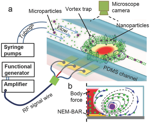
Using lasers can be problematic in cases where the heat builds up to the point where it can sometimes denature biologics. Cui et al., addressed this problem by using a novel hypersonic-induced hydrodynamic tweezer. A hypersonic resonator was used in a microfluidic device to create micro vortices which prove to be effective in trapping small particles. The overall setup of the device can be seen below in Figure 4. Polystyrene particles of varying size were used to test the effectiveness of the trapping. It was shown that the device can effectively be used to trap particles on the micro and nano scale [10]. However, nanoparticles require a larger trapping area. Additionally, particle rotation was studied using Janus particles and it was found that the rotation of the particles could be accurately tuned. Lastly, the researchers wanted to test the effectiveness of releasing the particles continuously in-line. Slowing down or turning off the vortex, allows the particles to be released in a controlled manner. The path of the particles is defined by the drag force of the bulk fluid flow in combination with the inertia established from the rotational flow.

References
- Chiou, P. Y.; Wu, M. C.; Ohta, A. T. Massively parallel manipulation of single cells and microparticles using optical images. Nature 2005, 436, 370-372. DOI: 10.1038/nature03831
- Neuman, K. C.; Block, S. M. Optical trapping. Rev Sci Instrum 2004, 75, 2787-2809. DOI: 10.1063/1.1785844
- Shenoy, A.; Rao, C. V.; Schroeder, C. M. Stokes trap for multiplexed particle manipulation and assembly using fluidics. PNAS 2016, 113, 3976-3981. DOI: 10.1073/pnas.1525162113
- Taylor GI (1934) The formation of emulsions in definable fields of flow. Proc R Soc Lond A Math Phys Sci 146(858):501–523.
- Tanyeri M, Johnson-Chavarria EM, Schroeder CM (2010) Hydrodynamic trap for single particles and cells. Appl Phys Lett 96(22):224101. DOI: 10.1063/1.3431664
- Pironneau, O. On optimum profiles in Stokes flow. Journal of Fluid Mechanics 1973, 59, 117-128. DOI: 10.1017/S002211207300145X
- Būtaitė, U. G.; Gibson, G. M.; Ho, Y. D.; Taverne, M.; Taylor, J. M.; Phillips, D. B. Indirect optical trapping using light driven micro-rotors for reconfigurable hydrodynamic manipulation. Nature communications 2019, 10, 1215. DOI: 10.1038/s41467-019-08968-7
- Lee, T. J.; Lewallen, C. F.; Bumbarger, D. J.; Yunker, P. J.; Reid, R. C.; Forest, C. R. Transport and trapping of nanosheets via hydrodynamic forces and curvature-induced capillary quadrupolar interactions. Journal of colloid and interface science 2018, 531, 352-359. DOI: 10.1016/j.jcis.2018.07.068
- Cui, W.; He, M.; Yang, Y.; Zhang, H.; Pang, W.; Duan, X. Hypersonic-Induced 3D Hydrodynamic Tweezers for Versatile Manipulations of Micro/Nanoscale Objects. Particle & Particle Systems Characterization 2018, 35, 8. DOI: 10.1002/ppsc.201800068
- Fukuyama, T.; Nakama, S.; Maeda, Y. T. Thermal molecular focusing: tunable cross effect of phoresis and light-driven hydrodynamic focusing. Soft Matter 2018, 14, 5519-5524. DOI: 10.1039/C8SM00754C
