Dielectrophoresis - Kylee Klinkowski
Motivation
Dielectrophoresis (DEP) is an electrostatic phenomenon in which a nonuniform electric field created by electrodes interacts with polarizable suspended particles in order to control and manipulate particle movement [1]. Dielectrophoresis has various applications, especially in the biomedical field, including cell transfer, in vitro fertilization, and biological assays [2]. Dielectrophoresis has also been used for cell fusion, which has led to advances in crossbreeding, cancer immunotherapy, and biomedical research. Perhaps most prominently, dielectrophoresis is used to sort cells, and to characterize changes in the electrical properties of cells [2].
History

1966: Herbert Pohl and Ira Hawk use dielectrophoresis to separate live and dead yeast cells. The apparatus used consists of a single generator and a pair of electrodes, one being a needle, and the other a plate [3].
1970s: Dielectrophoresis slowly begins to gain momentum, with Pohl continuing to be the primary researcher of the technique. Pohl works with other researchers, such as Karan Kaler and Ronald Pethig, to develop a chapter on dielectrophoresis in Pethig's monograph (Figure 1) [3].
1980s: Publications produced are mainly on new types of cell separations accomplished using the technique. Electrodes used are machined or created using pins and rods that are placed within chambers containing pins and plates, or within conducting cylinders. This creates a nonuniform electric field along the length of the tube. In this way, positive dielectrophoresis traps one cell type on the inner rod, while negative dielectrophoresis repels the other cell type from the rod. Cells covering the rod are propelled by flow passing through the cylinder, and collected in a tube at the end of the rod. This arrangement of electrodes ultimately turns out to be the biggest limiting factor in dielectrophoretic separation; although the design is optimal for continuous flow-through, the electric field gradient is low [3].
Late 1980s: Ron Pethig's group designs micropatterned electrodes with intricately designed features that are used as part of an optical system to measure dielectrophoresis collection. This method produces low resolution, and is soon improved by John Tame, who creates the first microelectrode pattern to create areas of high and low field nonuniformity. Masa Washizu and Gunter Fuhr follow suit and publish papers describing microfabricated electrodes for dielectrophoresis. With the advent of microfabricated electrodes, voltages could be made smaller, electrodes could be made any shape, and the separation process could be observed using a microscope [3].
1991: Gunter Fuhr publishes a paper on the use of traveling electric waves to generate lateral dielectrophoretic forces. This eventually leads to the development of "biofactories on a chip." This technique exists through the early 2000s, until its limitations, such as power requirements, large-scale electrode arrays, and slow cell separation speed, become apparent [3].
1992: Armand Adjari and Jacques Prost use electrodes shaped like ratchets to induce Brownian motion. The technology has limited application, but its principles are later used to understand pumping via asymmetric electrodes. Peter Gascoyne, Fred Becker, and Ron Pethig present the first separation of cancer cells using microfabricated electrodes. The publication sets a precedent for future dielectrophoretic separations by using a cell solution pumped across an electrode array, with separation occurring at interdigitated electrodes. Cells experiencing positive dielectrophoresis are trapped along electrode glass, while cells experiencing negative dielectrophoresis pass through [3].
1997: Ron Pethig and Peter Gascoyne implement dielectrophoretic field-flow fractionation [3].
Present: Planar electrode separators are most commonly used. Electrodes are generally microfabricated on planar surfaces, on which a conducting film is patterned. Electrodes are encased in a channel and covered with a lid [3].
Mechanism of Dielectrophoresis
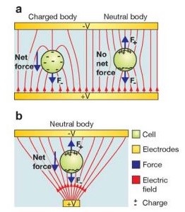
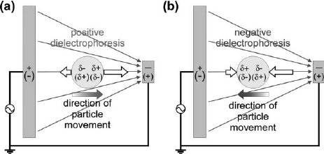
In an object containing both positive and negative charges, a dipole can be induced by changing the average positions of the positive and negative charges using an electric field [5]. According to Coulomb's law, a force acts on free charges. Therefore, a dipole in an electric field will experience forces applied to both positive and negative charges moving in opposite directions (Figure 2). If the electric field is uniform, then the forces acting on the dipole are equal and opposite, and the particle will not move. However, if the electric field is nonuniform, then the force on the charge at the higher electric field will be greater than the force on the charge in the lower electric field. Therefore, the direction of the particle is determined by the charge in the highest electric field. Positive dielectrophoresis occurs when particles are manipulated by forces acting in the direction of increasing electric field (polarizability of particle is greater than polarizability of medium), while negative dielectrophoresis occurs when particles are manipulated by forces acting in the direction of decreasing electric field (polarizabillity of particles is less than polarizability of medium) (Figure 3).
A particle in an electric field experiences the lateral force described in equation one [6]. [math]\displaystyle{ \bar{F}_\mathrm{elec} =q\bar{E}+(\bar{m}\nabla\bar{E}+\frac{1}{6}\nabla(\overrightarrow{Q}:\nabla\bar{E})+... (1) }[/math]
Where:
[math]\displaystyle{ \nabla }[/math] is the del operator
[math]\displaystyle{ q\bar{E} }[/math] is interaction between the net charge of particle [math]\displaystyle{ (q) }[/math] to the electric field [math]\displaystyle{ (\bar{E}) }[/math]
[math]\displaystyle{ \bar{m} }[/math] dipole force component
[math]\displaystyle{ \overrightarrow{Q} }[/math] is the Quadrupole Tensor
The time-averaged DEP force due to an imposed electrical field can be approximated in terms of dipole effects for a sphere using equation one [6].
- [math]\displaystyle{ \langle F_\mathrm{DEP} \rangle = 2\pi r^3\varepsilon_m \textrm{Re}\left\{\frac{\varepsilon^*_p - \varepsilon^*_m}{\varepsilon^*_p + 2\varepsilon^*_m}\right\}\nabla \left|\vec{E}_{rms}\right|^2 (2) }[/math]
Where
[math]\displaystyle{ \nabla \left|\vec{E}_{rms}\right|^2 }[/math] is the gradient of the square of the electric field quantifying the non-uniformity of the electric field
[math]\displaystyle{ 2\pi r^3\varepsilon_m }[/math] is the surface area of square
[math]\displaystyle{ {Re} }[/math] Takes real component of the Clausius-Mossotti Factor
[math]\displaystyle{ \varepsilon }[/math] permitivity
The Clausius-Mossotti Factor, equation 3, is the effective polarizability of the particle and its medium [8]
[math]\displaystyle{ \frac{\varepsilon^*_p - \varepsilon^*_m}{\varepsilon^*_p + 2\varepsilon^*_m} (3) }[/math]
Where
[math]\displaystyle{ \varepsilon^*_p, \varepsilon^*_m }[/math] is the complex dielectric characteristics of the particle and the medium [math]\displaystyle{ \varepsilon^*=\varepsilon=-j\omega\sigma }[/math] [8]
[math]\displaystyle{ \sigma }[/math] conductivity
[math]\displaystyle{ \omega }[/math] angular frequency
The above equation is simplified to reach the final form. The particles are considered to be homogeneous dielectrics and show no conductive losses. A simple dipole moment in an infinite medium is also assumed. The equation also does not take in account the presence of a boundary layer. However, this deviation portrays key features of the process. The DEP force is zero in a uniform electric field. The DEP force depends on the particle's volume; the greater the volume, the greater the force. Finally, the direction of the particle, towards or away from the electrode, is dependent on the medium and the particle’s permittivity [7]. The DEP force depends more on the conductive properties at low frequencies, and more on the permittivity values at high frequencies.
Whether a particle experiences positive or negative dielectrophoresis depends on the relative polarizability between the particle and medium, according to Maxwell-Wagner polarization [5]. Since force acting on a particle cannot be measured directly, a related property must be used to characterize polarizability. At the microscale, particles achieve maximum velocity in about 1 millisecond [5]. Since particle velocity is directly proportional to force, it can be used to characterize polarizability [5]. A number of methods have been used to measure particle velocity including image processing, electrorotation, crossover measurements, and collection rate studies, each method having its own pros and cons:
- Image processing: Particle velocity is compared to a known map of electric field strength
- Pro: Accurate
- Cons: Must know field gradient at every point, computationally intensive, only few particles can be used
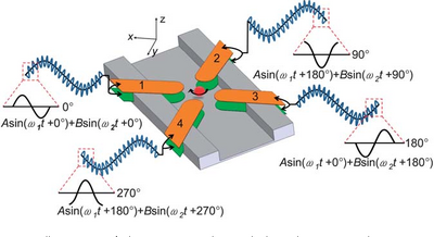
- Electrorotation: Velocity of the rotation of particles is measured when the electric field is rotated (Figure 4)
- Pro: Very accurate for single particles
- Con: Cannot be used for multiple particles
- Crossover measurements: Frequency where the dielectrophoresis force is zero is used to determine particle velocity
- Pro: Measurement easy to achieve
- Con: Only gives one measurable variable
- Collection rate studies: Count the number of particles at a point in a given period of time
- Pros: Simple, can use very large particle samples
- Con: Time consuming
Types of Dielectrophoresis
- Conventional Dielectrophoresis: Describes dielectrophoresis that is based upon Maxwell's electromagnetic field theory [2].
- Electrorotation: A particle is suspended in an electric field that rotates at an angular velocity and the particle is subjected to rotational torque [2].
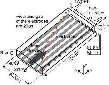
- Traveling-Wave Dielectrophoresis (TWDEP): A traveling-wave electric field is produced when phase-shifted voltages are applied to parallel electrodes, and the particle experiencing the traveling-wave field moves with or against the direction of the field (Figure 5) [2]. Particles suspended above two TWDEP electrodes move perpendicularly with respect to the electrodes [11]. Particle velocity and direction of movement along the electrodes are determined by the electrical properties of the particles used [11].
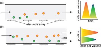
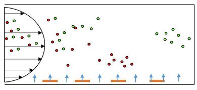
- Dielectrophoretic Field-Flow Fractionation (DEP-FFF): Since the dielectrophoretic force acting on a particle is proportional to the particle's size, many dielectrophoretic techniques are successful in separating particles by size (Figure 6) [12]. However, in some applications, it is useful to perform separation by exploiting differences in electric conductivity or dielectric permittivity of particles. In order to do so, dielectrophoretic field-flow fractionation uses the balance between the upward-pushing dielectrophoretic force and the downward-pulling dielectrophoretic force, caused by buoyancy and gravity [12]. In DEP-FFF, an electric force is applied to a liquid flow of particles, which moves particles to different heights in the flow chamber [12]. The height of each particle will vary according to a specified characteristic that is different between each particle type. Fluid flow is varied according to position such that different particles at different heights move at different speeds, and can be separated. Typically, particles are introduced at the bottom of a chamber, and negative dielectrophoresis is used to repel particles from the bottom of the chamber. The particles are repelled to a height proportional to the dielectrophoretic force acting on each particle, and the particles can then be removed [12].
Electrode Geometries
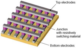
The four most common types of electrodes used for dielectrophoresis are listed below, each having different functions [13].
- Isometric: Effective for particle manipulation, but repelled particles do not collect in well-defined areas. Therefore, homogeneous separation is difficult to achieve.
- Polynomial: Produces well-defined differences in regions of high and low forces. Allows for particles to be collected by both positive and negative dielectrophoresis. This geometry allows for the highest electrical field to exist at the middle of inter-electrode gaps.
- Interdigitated: Uses alternating electrode fingers of opposing polarities. Mainly used for dielectrophoretic trapping.
- Crossbar: Used for networks of interconnects.
Advantages as a Microfluidic Separation Technique
- Dielectric force scales with characteristic length scale to -3 power
- Can be used to separate a variety of particles using one technique since particle response varies on frequency and phase of electric field
- Particle is not required to have a net charge
- Works between 1-100 μm
Applications
The first patent using DEP was granted in 1924 and was used for the separating minerals [15]. Comminution is an energy intensive process used in the mining process. Dielectrophoresis was reviewed as a better technique for the removal of course grains in order to lessen the amount of material going on to finer grinding processes [6]. Due to the properties of dielectrophoresis there is much interest in recent years to develop new technologies for applications in the study of micro-scale systems. The popularity of dielectrophoresis in micro-scale research is due to the fact that the required voltage requirements decrease with smaller length scales.
[math]\displaystyle{ F_{DEP}\approx V^2/L^3 }[/math]
When a system goes from a characteristic electric field length (L) of 1 cm to 100 μm, the voltage can be reduced by 1000 V while keeping the force constant. Therefore, one can achieve a higher force by decreasing the length of the system [6]. Current research is focused on how to manipulate and sort particles and analytes in microfluidic and micrototal analysis systems. DEP depends on many characteristics such as size and composition which makes the process tunable to specific mixtures. In addition, the process does not require expensive fabrication methods and the apparatuses can be produced with conventional electronics that eliminate the need for expensive and complex mechanical pumps [16]. DEP is mainly used as a characterization tool to collect rate, crossover and particle velocity measurements. Research in this topic is mainly concentrated within materials science and biotechnology. The aim is to incorporate DEP in devices to better study and control microscale systems [16].
Cell Separation
DEP depends on the structure and composition of a system, which allow for more complicated separations than in electrophoresis because of the electronic controllable focusing, translation, fractionation and characterization of analytes within a medium [17]. There has been a push to integrate DEP in microfluidic systems. It is due to the enhanced microelectrode structures that allow for the sorting of different cells and microorganisms using electric fields [18]. Positive and negative DEP are used to create devices for the sorting and patterning of different cells and other biological components.
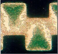
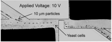
DEP technology has been used to separate a variety of different cell systems that include separating out bacteria, cancer cells, and viruses. Cells like particles have different electrical properties that include polarizability and net charge, which may be referred to as electrical phenotype [6]. The cell membrane/wall and cytoplasm contribute most to the cell’s overall induced charge. The first separation methods used the concept of negative and positive DEP. If cells have vastly different electrical properties then a frequency and a solution can be easily found where one type is forced towards the electrode and another away from the electrode. This method has been employed in a range of systems including the separation of viable cells from solutions, which uses a castell electrode design. Figure 3 shows the separation of deceased yeast cells. The dead cells which are stained green are raised off the plane with the living cells towards the electrode [19]. Figure 5 is a picture of a device that incorporates DEP into a microfluidic device where a side channel filled with buffer solution was able to sort viable and non-viable yeast cells without the need for another 3-D electrode fabrication step [20]. Similar methods have also been used in more complex systems, for example the separation of cells expressing the antigen CD34+ out of peripherial blood stem samples [21].
Separation is more difficult for cells with similar electrical properties. Techniques to separate these types of mixtures rely on the differences in magnitude of the Clausius-Mossotti factor. The primary way to separate cells using this method is called field-flow fractionation (DEP-FFF), which is shown in Figure 5 where there are a perpendicular and a parallel forces. The DEP force attracts one group of cells closer to the electrode then another in a parabolic flow channel, which enables one group of cells to go down the channel faster due to the differences in drag forces. One of the major benefits of this technique is that it is a one step process, unlike in techniques where cells have to be removed from specific electrodes. In essence, this method allows for the separation of closely related, complex cell mixtures [18]. There are also several limitations to this process. For smaller particles like viruses, Brownian motion comes into play and the pressure driven flow makes manufacturing these devices difficult.
Cell Handling
As shown above, electrode geometries can have a great effect on how to separate different cells. Initial devices were made out of sheets of metal. However one of the goals of current research is to lessen the voltage needed and these electrodes can be made through photolithography, laser ablation, and electron beam patterning [22]. Figure 3 represents one of the key geometries; there are areas of high and low forces which allow the particles to go through positive and negative DEP to settle. In addition to cell separation, devices are being made to trap and transport cells using DEP forces. The goal is to create an electrode design where there is zero net charge on the particle. Quadrupole electrodes have four electrodes with alternating voltage polarities applied to every other electrode to trap a particle. The video below shows insulating-post geometry where the insulating cyclical posts etched in a channel create field obstructions necessary for DEP [6]. There is a wide range of different research is being conducted to control the separation, pattern, and transport of cells.
Sorting of Protein Nanocrystals
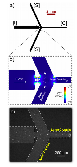
Dielectrophoresis has been used in combination with X-ray free-electron lasers (XFEL) to sort protein nanocrystals by size. XFEL has been used to uncover structures of proteins that cannot be solved using traditional crystallography [23]. Although a powerful method for solving protein structures, optimization of XFEL is necessary for improvement of data quality and analysis efficiency. More specifically, sample heterogeneity and variations in crystal size lead to the requirement of large data sets, and consequently require large samples of protein (10-100 mg) in order to accurately determine protein structure. In order to decrease sample disparity, researchers at Arizona State University developed a high-throughput microfluidic sorter that used dielectrophoresis to transport polydisperse particles into various fluid streams for size fractionation. Using this method, several milliliters of photosystem I nanocrystal fractions ranging from 200 to 600 nm in size could be isolated (Figure 11). The system obtained diffraction to ~4 A resolution, and small crystals were not damaged by the sorting process. Additionally, researchers were also able to observe shape transforms of the photosystem I crystals, meaning that the device could optimize data collection for the shape transform-based phasing method. Overall, the device allowed for automated size-sorting of protein crystals that could lead to reduction of the amount of protein needed for a high quality final structure analysis [23].
Other Applications
Although the most publications regarding DPS revolve around separation of cells, this process can be applied to any neutral particle. For example it has been shown that DEP can be used in metallic nanotubes separation and micro-structures assembly, which could have a large impact in the semi-conducting industry [22]. DPS is applied in the pattering, tapping and filtering of carbon nanotubes, nano-spheres, polystyrene, and silica particles. DPS is also being used in filtering and determining the concentration of crystallized proteins [24].
References
[1] Jones, T. IEEE Engineering in Medicine and Biology Magazine 2003, 22 (6), 33–42. http://dx.doi.org/10.1109/memb.2003.1304999.
[2] Qian, C.; Huang, H.; Chen, L.; Li, X.; Ge, Z.; Chen, T.; Yang, Z.; Sun, L. International Journal of Molecular Sciences 2014, 15 (12), 18281–18309. http://dx.doi.org/10.3390/ijms151018281
[3] Hughes, M. P. Biomicrofluidics 2016, 10 (3), 032801. http://dx.doi.org/10.1063/1.4954841
[4] Bunk, S. Dollars for Your Thoughts https://www.the-scientist.com/?articles.view/articleNo/13936/title/Dollars-for-Your-Thoughts/ (accessed Feb 10, 2018).
[5] An Introduction to Dielectrophoresis http://www.dielectrophoresis.net/dielectrophoresis/4583576344 (accessed Feb 9, 2018).
[6] Voldman, J. Annual Review of Biomedical Engineering 2006, 8 (1), 425–454. Doi:http://dx.doi.org/10.1146/annurev.bioeng.8.061505.095739
[7] Pethig, R. Journal of The Electrochemical Society 2016, 164 (5). Doi: http://dx.doi.org/10.1149/2.0071705jes
[8] Hsu, T.-R. MEMS and microsystems: design, manufacture, and nanoscale engineering; John Wiley: Hoboken, NJ, 2008.
[9] Pamme, N. Lab on a Chip 2008, 7 (12), 1644–1659. http://dx.doi.org/10.1039/b712784g
[10] Han, S.-I.; Joo, Y.-D.; Han, K.-H. The Analyst 2013, 138 (5), 1529. http://dx.doi.org/10.1039/c3an36261b
[11] Driesche, S. V. D.; Rao, V.; Puchberger-Enengl, D.; Witarski, W.; Vellekoop, M. J. Sensors and Actuators B: Chemical 2012, 170, 207–214. http://dx.doi.org/10.1016/j.snb.2011.01.012
[12] Cemazar, J.; Kotnik, T. Dielectrophoretic Field-flow Fractionation (DEP-FFF) http://www.aesociety.org/areas/dff_fractionation.php (accessed Feb 10, 2018).
[13] Huang, Y.; Pethig, R. Measurement Science and Technology 1991, 2 (12), 1142–1146. http://dx.doi.org/10.1088/0957-0233/2/12/005
[14] Green, J. E.; Choi, J. W.; Boukai, A.; Bunimovich, Y.; Johnston-Halperin, E.; Deionno, E.; Luo, Y.; Sheriff, B. A.; Xu, K.; Shin, Y. S.; Tseng, H.-R.; Stoddart, J. F.; Heath, J. R. Nature 2007, 445 (7126), 414–417. http://dx.doi.org/10.1038/nature05462
[15] Pethig, R. Biomicrofluidics" 2010, 4 (3), 039901. Doi: http://dx.doi.org/10.1063/1.3474458
[16] Gascoyne, P. R. C.; Vykoukal, J. Electrophoresis 2002, 23 (13) http://dx.doi.org/10.1002/1522-2683(200207)23:13
[17] Kadaksham, J.; Singh, P.; Aubry, N. Fluids Engineering 2003. Doi: http://dx.doi.org/10.1002/1522-2683(200207)23:13
[18] Pethig, R.; Markx, G. Trends in Biotechnology 1997, 15 (10), 426–432. Doi: http://dx.doi.org/10.1016/s0167-7799(97)01096-2
[19] Markx, G. H.; Pethig, R. Biotechnology and Bioengineering 1995, 45 (4), 337–343. Doi: http://dx.doi.org/10.1002/bit.260450408
[20] Suehiro, J.; Pethig, R. Journal of Physics D: Applied Physics 1998, 31 (22), 3298–3305. http://dx.doi.org/10.1088/0022-3727/31/22/019
[21] Talary, M. S.; Mills, K. I.; Hoy, T.; Burnett, A. K.; Pethig, R. Medical & Biological Engineering & Computing 1995, 33 (2), 235–237.Doi: http://dx.doi.org/10.1007/bf02523050
[22] Maria Dimaki and Peter Bøggild. Nanotechnology 2004 15 1095 http://dx.doi.org/10.1088/0957-4484/15/8/039
[23] Abdallah, B. G.; Zatsepin, N. A.; Roy-Chowdhury, S.; Coe, J.; Conrad, C. E.; Dörner, K.; Sierra, R. G.; Stevenson, H. P.; Camacho-Alanis, F.; Grant, T. D.; Nelson, G.; James, D.; Calero, G.; Wachter, R. M.; Spence, J. C. H.; Weierstall, U.; Fromme, P.; Ros, A. Structural Dynamics 2015, 2 (4), 041719. http://dx.doi.org/10.1063/1.4928688
[24] Çetin, B.; Li, D. Electrophoresis 2011, 32 (18), 2410–2427. http://dx.doi.org/10.1002/elps.201100167
