Capillary Valves - Jeremy Allen, Joshua McGee
Introduction
Capillary Valves are passive non-mechanical valves that utilize interfacial surface tension to block or restrict flow in a channel. Unlike Pneumatic Valves, capillary valves operate without moving parts. Utilizing capillary flow, devices can be fabricated that do not require external flow sources. Capillary valves have become very important with the integration of paper microfluidics for low-cost applications. Some valves, like electrowetting valves can be very advanced and costly for simple microfluidic devices like paper microfluidics. Capillary valves take advantage of forces that are created by the solid-liquid interface from liquid contact with a solid surface. Capillary flow is passive and does not require an additional application of force to move a liquid. This flow occurs as a result of liquid interaction with a "wettable" surface. The basic idea is an attempt to minimize surface energy. The energy that is stored in the surface is a function of surface area. To minimize the interfacial energy, the fluid will attempt to maximize its surface area (See: design theory). The interface between the liquid and solid, stores less energy than the air and solid so the liquid will move towards the less energetic state along the surface.1 This phenomenon can be utilized to create devices capable of passively filling. By inducing an abrupt change in geometry or hydrophobicity, a liquid can be stopped at a capillary valve. Depending on the materials used, methods of bypassing a capillary valve include: applying a burst pressure, reverting channel geometry, and changing temperature.
The integration of capillary valves in microfluidics creates the ability to have complex fluidic circuits. Capillary valves can be used to meter substances in small volumes for applications including protein crystallization and analyte detection.9,12
Background and Methods
The Interface
An interface is a clearly defined region between two distinct phases. In the case of microfluidics, it usually represents the solid channel and liquid species boundary. Molecules of the liquid will experience an attractive force coming from other molecules of the liquid (polar interactions, van der Waals forces) and an attractive force coming from the solid channel. These forces will differ in magnitude, creating what is known as surface tension.11 Surface energy, also known as interfacial free energy, is a measure of the forces at the interface of two components. Surface energy can also be defined as the work required to increase the unit surface area at constant temperature and pressure. As seen in Figure 1, when a liquid drop is added to a hydrophobic material it will bead up to minimize its surface area, minimizing surface energy.11 When a liquid drop is added to a hydrophilic material, it will increase its surface area to minimize surface energy.
When there is capillary flow through a microchannel, surface energy is minimized. There is high solid surface energy and low liquid surface energy, resulting in wicking of fluid. In this instance, the surface energy is minimized when the liquid increases its surface area. It is this minimization of free energy that allows the liquid to move passively along the channel. When the liquid reaches an abrupt change in geometry or hydrophobicity, the contact angle of the liquid and solid interface is changed. Using this concept allows for the construction of capillary valves that can be configured to obtain a variety of different valving conditions. The ability of the valve to stop the liquid can be determined using the Young-Laplace equation (See: design theory). By designing a capillary valve properly, the pressure required to burst it can be determined mathematically.
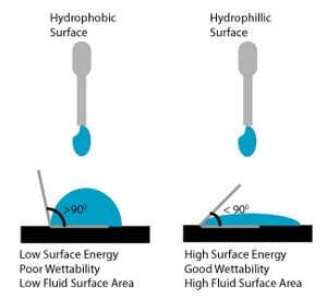

There are two main methods of capillary valves, local changes of contact angle and local changes of surface geometry. These two methods are both driven by the change in surface and liquid interface either by changing the surface angle or the surface properties.2
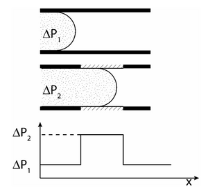

Change in Hydrophobicity
The local change in contact angle can be summarized as the change of surface interface which will change the pressure need to push the liquid along. If the surface increases in hydrophobicity there is a larger pressure needed to push the liquid past that point which gives it the properties of a valve (Figures 1,2). A hydrophobic surface will cause the angle of the solid-liquid interface to be greater than a hydrophilic surface and prevent the liquid to be pushed by the surface forces.2 This is a result of the liquid attempting to minimize surface energy with the solid by decreasing its surface area, resulting in the formation of a bead. A hydrophobic surface can be created by applying a hydrophobic material to a portion of the microchannel. This has been done using an inkjet printer to apply hydrophobic ink to a defined area. Another method is using a pH-sensitive hydrogel that can change in hydrophobicity.
See more at hydrophobic valves.
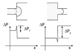
Change in Geometry
A local change in geometry can change the contact angle of the liquid as in Figures 3,4, which will change the pressure needed to push the liquid along. The barrier needed to push the liquid across this change in contact angle is called the burst pressure. This is usually a less effective method for capillary valves so it is combined with the other method of adding a hydrophobic surface.5
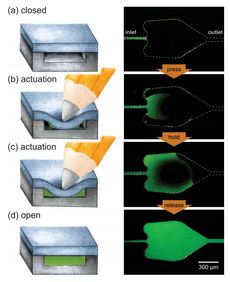
Capillary stop valves are used to stop flow in a channel using a sudden divergence of the channel cross-section. This divergence usually means a constriction in the channel followed by sudden enlargement (See Figure 5). This change in geometry results in a change in the contact angle between the liquid and the solid interface, stopping the wicking of the fluid. The pressure difference required for the fluid to resume flow can be calculated in terms of the channel geometry and contact angle of the liquid at the point of divergence (See: capillary pressure). To restart capillary flow an external pneumatic or centrifugal force must be applied. The geometry of the valve can also be reverted using soft capillary valves. This process is important for biological process that cannot be interfered with by hydrophobic interfaces.4 Biological applications that involve proteins will suffer from hydrophobic collapse, strong hydrophobic interactions between the protein and the superhydrophobic surface. Capillary soft valves use the idea of the local change in geometry to prevent flow and are activated by simply compressing the valve to change the shape. This causes the liquid to fill the valve and flow is continuous. The flow cannot be stopped once the valve is compressed and liquid flows through.6
Alternative Methods
Surface energy is a function of temperature. The work required to change the surface area of a liquid can be increased or decreased through modification of temperature. Using this idea, an alternative method to create a capillary valve involves changing the temperature of a microfluidic channel. Heating a material over the channel such as wax can stop the flow or the opposite can be used where the liquid is locally frozen causing the flow to stop. These valves require more equipment and can interfere with the liquid species.3
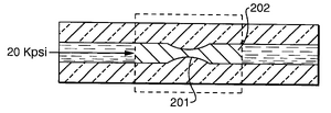
Freezing/thaw valves use a thin channel that has a freeze plug and when axial force is applied will constrict (Figure 6). These valves are used for narrow bore capillaries.This is important for high-pressure applications that can cause valve leaking. The decrease in temperature can affect the substance though so this valve can only be used in certain applications. To stop flow liquid carbon dioxide or liquid nitrogen can be used. To heat and melt the liquid freeing flow, a hot stream of air or electrical current can be applied.7
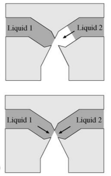
Another example of valves that use the above principles is liquid triggered valves. These have two channels that join together at capillary valves that function by introducing a sudden constriction in the channel. One of the liquids is flown into the device first and is stopped at the capillary valve. The liquid flow only resumes when the "trigger liquid" (the other liquid) is flown into the device. These valves are very useful to ensure air bubbles are not trapped in the fluid.8
Design Theory
Surface Wetting
When constructing a microfluidic capillary valve, it is important to consider that a surface is considered wettable if a specific liquid contacts it at an angle of <90 degrees.9 A contact angle >90 degrees means that a surface is not very wettable and liquid will bead up to minimize surface area and surface energy respectively. Liquids will have different wetting angles depending on their chemical composition as well as the composition of the microfluidic device material. The wettability of commonly used microfluidic materials is well documented in the literature.

Capillary Pressure
Capillary pressure is the result of surface tension at the solid-liquid interface. For a wettable material, the capillary pressure induces a negative pressure force, which creates a wicking effect for the liquid. Microfluidic devices are typically fabricated using photolithography, often creating rectangular channels. Capillary pressure for microfluidic channels can be calculated using the Young-Laplace equation9:
[math]P = -\gamma ([\frac{cos(\theta_ t)+cos(\theta_ b)}{h}]+[\frac{cos(\theta_ l)+cos(\theta_ r)}{w}])[/math]
[math]\gamma [/math] : surface tension of liquid in microchannel
[math] h[/math] : height of microchannel
[math] w[/math] : width of microchannel
[math]cos(\theta_ t) [/math] : contact angle with top of microchannel
[math]cos(\theta_ b) [/math] : contact angle with bottom of microchannel
[math]cos(\theta_ l) [/math] : contact angle with left side of microchannel
[math]cos(\theta_ r) [/math] : contact angle with right side of microchannel
Positive capillary pressure indicates capillary flow and negative capillary pressure indicates high interfacial surface energy, causing the fluid to be repelled from the channel.11 Evident by this equation is the fact that as microchannel dimensions decrease, capillary pressure increases. Using this as an advantage, decreasing the cross-sectional area abruptly will stop capillary flow. It is important that the contact angle is much less than 90 degrees. For contact angles near 90 degrees, the capillary pressure becomes relatively insignificant. If there are any imperfections in the channel, flow could be disrupted.9 It is recommended that a material is used that will result in a contact angle around 60 degrees. This will allow for the ability to create ideal capillary pressure.
For PDMS device bonded to glass:
[math]\frac{W}{H} > \frac{-2cos(\theta_P)}{cos(\theta_G)+cos(\theta_P)}[/math]
[math] H[/math] : height of microchannel
[math] W[/math] : width of microchannel
[math]cos(\theta_P) [/math] : contact angle with PDMS
[math]cos(\theta_G) [/math] : contact angle with glass
If this inequality is satisfied, capillary flow leading to spontaneous filling will occur.11 It is important that the correct aspect ratio is determined to allow for filling. For this, a wide and shallow channel will result in the best filling.
Stopping Flow
Once liquid is flowing in order to stop it a sudden enlargement in the microchannel must occur. This could be the junction between a metering channel and a reaction chamber.11 The pressure that must be overcome to “burst” the capillary valve can be calculated with the following general equation:
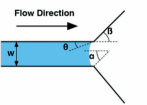
[math] \Delta P = \frac{2\gamma }{h}(\frac{cos\theta -\frac{\alpha *sin\beta }{sin\alpha }}{cos\beta +\frac{sin\beta }{sin\alpha }-cos\alpha }) [/math]
[math] \gamma [/math]: surface tension at solid liquid interface
[math] h[/math]: height of microchannel
[math] \theta[/math]: contact angle
[math] \alpha[/math]: liquid meniscus curvutare (lateral)
[math] \beta[/math]: change in curvature of liquid meniscus
Centrifugal Force
If a circular chip is used, centrifugal force is used to restart flow and meter a substance into a particular channel, the volumetric flowrate can be calculated using the following equation: source
To take advantage of centrifugal force, a lot of microfluidic devices are in a circular CD-like format. This allows for the device to easily be spun at a certain RPM using a spin-coater etc. The centrifugal force is a function of the RPM that the device is spun at, therefore the burst pressure can be applied by spinning at a particular RPM speed.
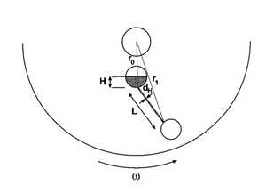
[math]Q = UA = \frac{Ad_h^2 \rho\omega ^2 \overline{r}\Delta r}{32\eta L}[/math]
[math]Q[/math]: volumetric flowrate
[math]U[/math]: linear velocity of liquid
[math]A[/math]: cross sectional area
[math]\rho[/math]: density of fluid
[math]\eta[/math]: viscosity of fluid
[math]d_h[/math]: hydraulic diameter of channel defined as: [math]4A/P[/math] where P is the perimeter of the channel and A is the area
[math]L[/math]: length of channel
[math]\overline{r}[/math]: distance from liquid to center of chip
[math]\omega[/math]: angular velocity
[math]\Delta r[/math]: radial extent of fluid
Applications
Protein Crystallization
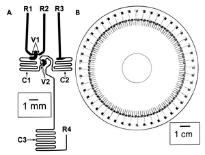
The ability to use capillary valves to meter reagents is very useful for protein crystallization where only a limited amount of protein can be used. Using capillary valves, nanoliter volumes can be dispensed into a reaction chamber and mixed with crystallization reagents. This allows for the screening of crystallization conditions in a cost-effective and high throughput manner. In 2010, Li et al. created a compact disk-like microfluidic device capable of screening multiple crystallization conditions simultaneously.12 A central inlet allows for the ability to fill and distribute protein to 24 chambers. The protein solution is stopped at a capillary valve. Crystallization solutions can then be filled into each of the reagent inlets. The crystallization solutions are also stopped at a capillary valve. Once the device is filled, a centrifugal force can be applied to meter the solutions in the reaction chamber. Since PDMS and glass are transparent, the resulting mixture can then be analyzed with optical microscopy to determine if crystallization has occurred.

Analytic Assays
The ability to create compact disk-like microfluidic chips can be used for a variety of analytical applications. Using centrifugal force to meter flow has been demonstrated to allow for flowrates ranging from 5 nl/s to 0.1 mL/s. The ability to precisely control flow is highly advantageous when working with expensive reagents for analytical chemistry. This method of driving fluid has been used for a variety of biological fluids as well as organic solvents.12 In 1999, Duffy et. al demonstrated the ability to create a microfluidic capillary device capable of performing 48 enzymatic assays at once.12 Using colourimetric detection the Michaelis constants of various enzymes were calculated.
References
1- Vowell, S. Microfluidics Effects of Surface Tension. 2009-03-19)[2010-09-21].
2- Li, D. Encyclopedia of microfluidics and nanofluidics; Springer Science & Business Media: 2008;
3- Tsougeni, K.; Papageorgiou, D.; Tserepi, A.; Gogolides, E. “Smart” polymeric microfluidics fabricated by plasma processing: controlled wetting, capillary filling and hydrophobic valving. Lab on a Chip 2010, 10, 462-469.
4- Maria, M. S.; Rakesh, P.; Chandra, T.; Sen, A. Capillary flow-driven microfluidic device with wettability gradient and sedimentation effects for blood plasma separation. Scientific reports 2017, 7, 43457.
5- Gliere, A.; Delattre, C. Modeling and fabrication of capillary stop valves for planar microfluidic systems. Sensors and Actuators A: Physical 2006, 130, 601-608.
6- Hitzbleck, M.; Avrain, L.; Smekens, V.; Lovchik, R. D.; Mertens, P.; Delamarche, E. Capillary soft valves for microfluidics. Lab on a Chip 2012, 12, 1972-1978.
7- Gerhardt, G. C.; Bouvier, E. S.; Dourdeville, T. Fluid flow control freeze/thaw valve for narrow bore capillaries or microfluidic devices 2003. ( I could not find a DOI for this source)
8- Oh, Kwang W., and Chong H. Ahn. "A review of microvalves." Journal of micromechanics and microengineering 16, no. 5 (2006): R13.
9- Olanrewaju, A., Beaugrand, M., Yafia, M., & Juncker, D. (2018). Capillary microfluidics in microchannels: from microfluidic networks to capillaric circuits. Lab on a Chip, 18(16), 2323-2347.
10- Vowell, Schuyler. (2019). Microfluidics: The Effects of Surface Tension.
11- Li, G., Chen, Q., Li, J., Hu, X., & Zhao, J. (2010). A compact disk-like centrifugal microfluidic system for high-throughput nanoliter-scale protein crystallization screening. Analytical Chemistry, 82(11), 4362-4369.
12- Duffy, D. C., Gillis, H. L., Lin, J., Sheppard, N. F., & Kellogg, G. J. (1999). Microfabricated centrifugal microfluidic systems: characterization and multiple enzymatic assays. Analytical Chemistry, 71(20), 4669-4678.
