Pneumatic Valves - Alex Brosseau, Anthony Brouillard
Introduction
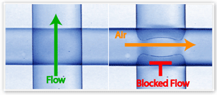
Valves are essential part of microfluidics because they allow for control of flow through microfluidic channels. Pneumatic valves are a common form of microvalve that is controlled mechanically by gas pressure (or a vacuum). They are active valves since they rely on mechanical force from fluid pressure or a vacuum. Pneumatic valves commonly involve a flexible membrane that controls the flow through a channel.1 Stephen Quake and coworkers introduced the first pneumatic microvalve in 2000.1,2,3,4 Since then pneumatic valves have gained wide spread popularity. The popularity of pneumatic valves is largely due to their easy integration in soft lithography designs. Pneumatic valves are widely used, but require careful design considerations in order to successfully integrate them into a device.
General Overview of Pneumatic Valves
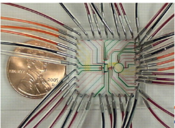
A microfluidic pneumatic valve is generally made of PDMS (polydimethylsiloxane), a soft material that is widely used as stamp resin for Soft Lithography. For example, Stephen Quake's group design uses the deformation of PDMS as a way to interrupt the flow in channel. In Quake's design, a control line is usually connected to a external gas supply. When the external gas supply is turned on the pressure from the gas exerts a force on the PDMS membrane. As demonstrated in Figure 1, the deformation of the PDMS causes the channel perpendicular to the control line to close shut. Occasionally, a liquid is used in the control line instead of a external gas source. Pneumatic valves can be very cumbersome due to the need for many external gas tank connections to the device (as shown by Figure 2). Also, a separate solenoid valve is needed in order to adjust the pressure of the gas. According to Mohan et al., the pressure needed to actuate a valve is largely determined by the membrane stiffness.6 Mathematical models for estimating membrane stiffness have been developed by researchers such as by Desai et al. This work determined model for membrane stiffness for further use in electrostatic valves, but the equations for membrane stiffness still apply to rectangular or circular channel bilayer elastic membrane valves, in general.5 For example:
[math]\displaystyle{ k= K_{bilayer} K_{post} \frac{K_{MS}}{K_{AR}} (K^{1}_{shape}\frac{E_{bm}t^{3}_{m}}{D^{4}}+K^{2}_{shape} \frac{st_{m}}{D^{2}}) }[/math]
[math]\displaystyle{ k = }[/math] static membrane stiffness per unit area of membrane
[math]\displaystyle{ E_{bm} = }[/math]biaxial stiffness
[math]\displaystyle{ t_{m}= }[/math]total thickness of the membrane
[math]\displaystyle{ D= }[/math] membrane diameter or length
[math]\displaystyle{ K_{bilayer} }[/math]= factor to account for bilayer setup
[math]\displaystyle{ K_{post} }[/math]= factor account for cylindircal support post (inherent to Desai et al. design)
[math]\displaystyle{ K_{MS} }[/math]= factor to account for bilayer setup
[math]\displaystyle{ K_{AR} }[/math]= factor to account for aspect ratio
[math]\displaystyle{ K_{shape} }[/math]= factor to account for shape of channels (rectangular or circular)
[math]\displaystyle{ s }[/math]= residual stresses
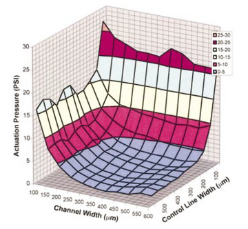
The model for the membrane stiffness, developed by Desai et al., relies upon many assumptions.5 These assumptions are the membrane is homogenous and uniformly thick; the deformation of the membrane is completely elastic; membrane displacement due to transverse shear is negligible; the Poisson’s ratios of the two layers making up the bilayer membrane are not significantly different (two layers are made up on PDMS); the expressions for static stiffness of the membrane can be used to estimate the stiffness of the membrane during dynamic operation of microvalves; and the membrane is perfectly clamped along the complete outer edge. Using an analytical solution for membrane stiffness, a force balance for specific geometry of valve can be used to determine an actuation pressure. Alternatively, Studer et al. used numerical finite element solution to differential equations governing a specific valve geometry. A plot of the relationship between actuation pressure, fluid channel width, and control channel width for particular valve geometry determined by numerical methods is shown by Figure 3.2 As shown by Figure 3, wider fluid and control channels require a smaller actuation pressure to deform the membrane. This is similar to how buildings that are large need to be supported by column while small buildings do not.
Types of Pneumatic Valves
There exists two types of pneumatic valves: normally open (actuate-to-close) and normally closed (actuate-to-open).
Normally Open (Actuate-to-close) Valves
Normally open valves slow flow only when they are actuated. When the valve is actuated the fluid in the control line puts pressure on the membrane so that it blocks the flowing fluid channels path. There are three types of normally open microvalves that are commonly used: the Quake valve, the plunger valve, and lateral deflection valve.1,2,3,4
Quake Valve
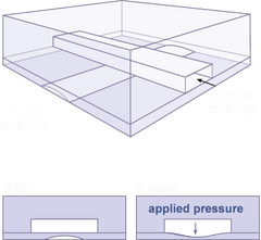
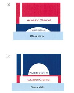
Quake valves are pneumatic valves that are used often. Quake valves are made of three layers: one layer for control channel, another for fluid channel and bottom layer (as shown by Figure 4). The valve is made of a single control channel that overlaps a semicircular fluid channel and is separated by a membrane thickness of around 5-15 micrometers.1 In all Quake valves the fluid channel is perpendicular to the control (actuation) channel. Many different versions of the Quake valve have been developed over the years. The Quake valve can be categorized by being either push up or push down, as shown by Figure 5. In a push up valve the membrane separating the control channel and fluid channel deforms downward to close fluid channel below it. In a push up valve the membrane deforms upwards to seal a fluid channel above it. A push down valve requires a large aspect ratio of the fluid channel, and can use many types of substrates. The push up design can has wider variability in thickness due to its independence of channel dimensions, require lower actuation pressures, and membrane thickness is uniform. Quake valves are commonly used for PCR, protein separation and cell sorting.1 The Quake valve has disadvantages in that it is not the best for imaging and flow regime determination. The semicircular fluid channel acts like a lens. It distorts light, like of visible and UV spectrum, that is used for imaging. The deformed semicircular characteristic of the Quake valve when put under pressure also makes it not have an analytical solution for its flow regime. This makes designing a Quake valve for a particular flow regime like laminar flow difficult due to the lack of predictive behavior. Numerical modeling by computers is often employed for the valve's flow regime.
Plunger Valve
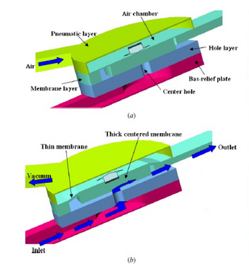
A plunger valve is designed like a larger scale plunger would be. In a plunger valve, a plunger it attached to a circular hole.1,8 When open, fluid flows through the circular hole through multiple layers, as shown by Figure 6. The valve layer, when it gets a pneumatic signal, plunges into the hole the fluid travels through and blocks its path. An SU-8 disk can be integrated into the Plunger valve to allows for higher pressures. Plunger valves are often used to develop logic gates in a microfluidic device. They are also used to make a microneedle for microinjections.1
Lateral Deflection Valve
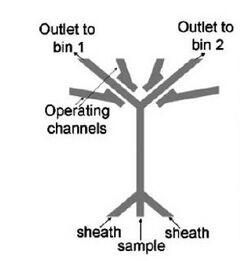
A lateral deflection valve consists of a single layer, shown by Figure 7. Both the control channel and fluid channel are in this layer and are separated by a small gap of membrane, typically 14 micrometers in thickness.1 When control channel(s) is actuated the pressure pushes the membrane blocking the fluid channel next to it. Lateral deflection valves are advantageous because they are simpler to fabricate because they consist of only a single layer. The problem with lateral deflection valves is they cannot fully close a channel, rather they can only resist flow.1 One application of lateral deflection valves is high speed cell sorting.
Line Valve
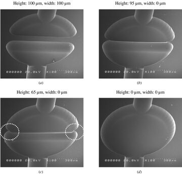
A line valve is designed in a way that it can overcome the limitations of a normally-open, which is potentially bonding between the membrane and the substrate upon actuation, permanently shutting the valve. Overcoming this allows for the valve to be used at a variety of fluid pressures without leaks or fusing9. The Park group has designed an in-line microvalve that is actuated by external pneumatic methods. Instead of using a flat plane in order to close the valve (Figure 8, A), it utilizes a one-dimensional line which is wet-etched from a valve seat (Figure 8, B and C). This wet-etching process makes PDMS unable to bond to the membrane causing permanent locking. Other methods use metals, salts, or oligomeric coatings to inhibit sticking of the seat, but that is where this valve has the advantage over others. This design incorporated a sharp microstructure at the peak of the seat, minimizing contact with the PDMS structure and discouraging binding9, maintaining its purpose as normally opened and allows for more fluid flow at higher pressures.
Normally Closed (Actuate-to-open) Valves
Pneumatic valves can be designed to be closed at rest. These types of valves are called normally closed valves. Normally closed valves tend to have a rectangular shape. Three type of normally closed valves include doormat, curtain, and check valves. Normally closed valves require only one type of photoresist to fabricate, unlike normally open valves, because of their rectangular channel design. One problem with normally closed valves is that when they are assembled there is high chance they can be accidentally permanently closed shut.1 Normally closed valves are made usually by SU-8 photolithography which allows for sharp rectangular channels. Since there is no need for curved PDMS in normally closed valves the resolution of the channels is not affected by poor curvature in PDMS, and the imaging quality can be much higher.

Doormat Valve
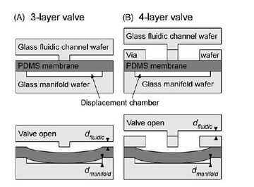
The Doormat valve is a normally closed valve that utilizes a vacuum to open the valve.1 The original doormat design was done by Hosokawa et al., shortly after Quake valve was developed.15 The design consisted of 3 PDMS layers with fluid and control channels separated by PDMS membrane "doormat" that sags into fluid channel. When a vacuum is applied the membrane moves downward and opens the fluid channel. Another design of doormat valve is the Mathies Valve which consists of glass and PDMS rather than just PDMS.14 The Mathies layer, unlike Quake valve, confronts the problems associated with all elastomer valve by having 3 or 4 layers that consists of glass and PDMS. All the channels are rectangular and work by applying a vacuum in "displacement" chamber to cause the inner PDMS membrane to fall downward to open fluid channel, like Hosokawa valve, as shown by Figure 9. Mathies Valves are primarily designed for devices that require clear material substance like glass so imaging techniques like UV Vis can be used.
Curtain Valve
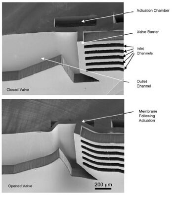
The curtain valve is very similar to the doormat valve, but it has a slightly different geometric design that allows for valve opening due to a vacuum. As shown by Figure 10, the applied vacuum in actuation channel causes the inlets to fold due to PDMS membrane deformation so that they can flow into the outlet channels.18 These valves are commonly used for cell enrichment and separation.1
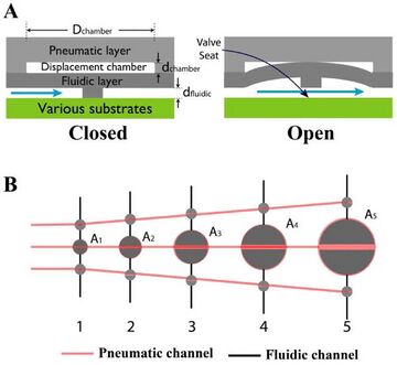
Another version of the doormat valve is the “lifting gate” microvalve proposed by the Kenis group17. This type of microvalve utilizes vacuum-driven fluid flow, lifting away a fluidic layer towards a pneumatic layer to enable flow along various substrates (shown in Figure 11,A). Similar to the doormat valve, this incorporates a three-layer design. This is made using SU-8 soft-lithography molds to create the pneumatic and fluidic layers. This microvalve was operate by applying a vacuum to the inlets of the pneumatic layer through a series of off-chip solenoid controllers. In this study, the pumping capability was evaluated with five various-sized pumps, and the pump performance was characterized by the displacement of the chamber volume (Figure 11,B)17. The volume pumped per cycle depends on the manifold valve volume (center) in the three-valve pump series shown in Figure 11, B. Vmax, the theoretical maximum volume pumped per cycle is dependent on the volume of the fluidic region on the downstream side of the gate. Vmax was calculated as shown17:
[math]\displaystyle{ V_{max} = \frac{1}{4} π D^{2}_{chamber} d_{manifold} + A_{i} d_{fluidic} }[/math]
Where [math]\displaystyle{ d_{mannifold} }[/math] is the depth of the manifold displacement chamber, [math]\displaystyle{ D_{chamber} }[/math] is the diameter of the manifold valve displacement chamber, [math]\displaystyle{ d_{fluidic} }[/math] is the depth of the fluidic channel, and [math]\displaystyle{ A_{i} }[/math] is the half area of the fluidic chamber. The application of gates like this can be used for automating microparticle label immunoassays, which looks for specific binding of microparticles to a given substrate.
Check Valve
The check valve is only normally closed valve listed here that does not use a vacuum source. Rather, the check valve consists of a fluid flowing in one way in fluid channel. Increases in the flowing fluid pressure causes the channel to open. Figure 12 is an example of a check valve called a flap valve. In the flap valve, the fluid in channel has higher pressure than reactant. When reactant pressure is greater than other fluid's pressure is increased the flap valve opens and the two flow into the same channel. The flap valve has its disadvantages due to it relying on laminar flow so two do not fully mix.1 However, in the case of reaction this is an advantage. As a result, flap valves are commonly used for reactions in microfluidic devices. These valves are expensive, but the cost will decrease when commercialized due to benefits of scale.18
| Pros | Cons | Applications | |
|---|---|---|---|
| Normally-Open |
|
|
|
| Normally-Closed |
|
|
|
Fabrication and Design Considerations for Pneumatic Valves
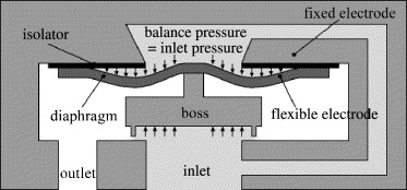
Normally open valves like the Quake Valve are more complex to develop by photolithography and soft lithography because they require more than one photoresist for silicon masters due to the rounded PDMS for channels than normally closed valves. When making the actuation channel pattern SU-8 is commonly employed as negative photoresist. Shipley AZ100 XT, a positive photoresist, is used for the flow channel. The positive photoresist allows for the formation of curved pattern. Due to the use of positive photoresist the channel width and height cannot be designed separately. Further problems arise with normally open valves because rounded parts do not transfer from silicon to PDMS well. Normally closed valves only need SU-8 photoresist so the photolithographic process difficulty is greatly reduced. There are many design considerations that one must note when making the choice to use a pneumatic valve versus capillary, electrowetting valve etc. Pneumatic valves, as stated above, often have to have a external pressure source. These external pressure sources have to have solenoid valves themselves to regulate them. This means the process of controlling the device can just be completely done device which limits portability of the device. Also, if a device has many pneumatic connections it can get cumbersome, like in Figure 1. In order to overcome problems with too many connections multiplexing can be used. Some of these challenges have been overcome by use of multiplexing valves. Multiplexing relies on binary code and other forms of logic to create of system of logical valves that open and close depending on a received signal, can be electrical or pneumatic signal, to them. By receiving a certain signal a certain set of valves will open and close in the network of valves. This reduces the amount of connections needed for many pneumatic valves because the valves do not need as many gas pressure sources. Another design consideration is whether or not to combine pneumatic valve with electrostatic valve. This design is known as pneumatically balanced electrostatic valve.6,7 When a fluid flowing in a channel exerts higher pressure on its surroundings, a opposing high pressure fluid is a way to counteract the pressure of the fluid in the channel, as shown by Figure 13. Furthermore, in order to create an binary open and close situation for the fluid in channel, another actuation valve is needed than just high pressure opposing fluid. This valve can be a electrostatic valve that allows higher pressure fluid to be controlled.1
References
1-Au, A. K.; Lai, H.; Utela, B. R.; Folch, A. Microvalves and Micropumps for BioMEMS. Micromachines 2011, 2 (4), 179–220 DOI: 10.3390/mi2020179.
2-Studer, V.; Hang, G.; Pandolfi, A.; Ortiz, M.; Anderson, W. F.; Quake, S. R. Scaling properties of a low-actuation pressure microfluidic valve. Journal of Applied Physics 2004, 95 (1), 393–398 DOI: 10.1063/1.1629781.
3-Unger, M.A.; Chou, H.P.; Thorsen, T.; Scherer, A.; Quake, S.R. Monolithic microfabricated valves and pumps by multilayer soft lithography. Science 2000, 288, 113-116.
4-Thorsen, T.; Maerkl, S.J.; Quake, S.R. Microfluidic large-scale integration. Science 2002, 298, 580-584.
5-Desai, A. V.; Tice, J. D.; Apblett, C. A.; Kenis, P. J. A. Design considerations for electrostatic microvalves with applications in poly(dimethylsiloxane)-based microfluidics. Lab on a Chip 2012, 12 (6), 1078 DOI: 10.1039/c2lc21133e.
6-Mohan, R.; Schudel, B. R.; Desai, A. V.; Yearsley, J. D.; Apblett, C. A.; Kenis, P. J. Design considerations for elastomeric normally closed microfluidic valves. Sensors and Actuators B: Chemical 2011, 160 (1), 1216–1223 DOI: 10.1016/j.snb.2011.09.051.
7-Quero, J.; Luque, A.; Franquelo, L. A novel pressure balanced microfluidic valve. 2002 IEEE International Symposium on Circuits and Systems. Proceedings (Cat. No.02CH37353) 2002 DOI: 10.1109/iscas.2002.1011421.
8-Baek, J.Y.; Park, J.Y.; Ju, J.I.; Lee, T.S.; Lee, S.H. A pneumatically controllable flexible and polymeric microfluidic valve fabricated via in situ development. J. Micromech. Microeng. 2005, 15, 1015-1020.
9 - Kim, J.; Kang, M.; Jensen, E. C.; Mathies, R. A. Lifting gate PDMS microvlaves and pumps for microfluidic control. Anal. Chem. 2012, 84(4), 2067-2071. https://dx.doi.org/10.1021%2Fac202934x
10-Wijngaart, W. V. D.; Ask, H.; Enoksson, P.; Stemme, G. A high-stroke, high-pressure electrostatic actuator for valve applications. Sensors and Actuators A: Physical 2002, 100 (2-3), 264–271 DOI: 10.1016/s0924-4247(02)00070-5.
11-Lee, C.-C. Multistep Synthesis of a Radiolabeled Imaging Probe Using Integrated Microfluidics. Science 2005, 310 (5755), 1793–1796 DOI: 10.1126/science.1118919.
12-The Microvalve: The Traffic Light of Microfluidics https://www.microfluidicfuture.com/blog/microvalve-traffic-light-microfluidics.
13- Sundararajan, N.; Kim, D.; Berlin, A.A. Microfluidic operations using deformable polymer membranes fabricated by single layer soft lithography. Lab Chip 2005, 5, 350-354. DOI:10.1039/B500792P
14- W.H. Grover, A.M. Skelley, C.N. Liu, E.T. Lagally, R.A. Mathies, Monolithic membrane valves and diaphragm pumps for practical large-scale integration into glass microfluidic devices, Sensors and Actuators B: Chemical 89 (2003) 315–323. DOI: 10.1016/S0925-4005(02)00468-9
15-Hosokawa, K.; Maeda, R. A pneumatically-actuated three-way microvalve fabricated with polydimethylsiloxane using the membrane transfer technique. J. Micromech. Microeng. 2000,10, 415-420.
16- Irimia, D.; Toner, M. Cell handling using microstructured membranes. Lab Chip 2006, 6,345-352. DOI:10.1039/b515983k
17- Park, C.; Hwang, K.; Jung, W.; Namkoong, K.; Chung, W.; Kim, J.; Huh, N. A PDMS membrane microvalve with one-dimensional line valve seat for robust microfluidics. Journal Micromech Microeng 2014, 24, 2.
18- Voldman, J.; Gray, M.L.; Schmidt, M.A. An integrated liquid mixer/valve. J. Microelectromech. Syst. 2000, 9, 295-302.
19 -Perry, S. Actuate-to-close; 2016.
