Biomod/2017/StJohns:Design
http://openwetware.org/images/f/f9/Lukemanlab-toehold-conga-nanny-header.jpg
Origami Design
XXXClawXXX
XXXHow much of this do we want to keep? Because we have the next section...XXX
In the assembly of our generic claw M13mp18 plasmid is used as a scaffold. This scaffold then is folded into the ‘Claw’ structure (Figure 2). There are 226 staple strands, which hold this structure together; the location of each can be pinpointed using the coordinates shown (Figure 3). Removing one of the original staple strands, and inserting another in which the sequence is only partially complementary to the region can create a sticky region. Taking into account the helical twist of DNA folding the positioning of the sticky end of the staple strand is crucial. The design of this Claw requires that the sticky ended region be an A21 series. Vanilla 'sticky' and 'blunt' claws were designed.
The design of NClaw required several of the original staple strands to removed in order to insert one donor and two acceptor sites for FRET (Fluorescence Resonance Electron Transfer) analysis. These sites were placed close to the hinged portion of the claw, allowing them to be close enough to visualize an energy transfer upon the closing of the claw. As a result when imaging the claw in an unbound position (Figure 2), there would be less energy at the acceptor sites, when compared to the closed [or bound] position (Figure 4). The donor and acceptor sites are closer together and thus are able to transfer and accept a greater energy transfer.
The original design of the Vanilla Claw and NClaw contained one binding site per arm, making a total of 3 for the entire claw. After not witnessing capsid-claw binding, via gel shift, it was decided that adding several binding sites/arm might increase the likelihood of the capsid successfully attaching, Experiments were carried out using two versions of 3 three binding sites, one in which the binding sites created a horizontal-facing triangle (<) and (>), the other in which the triangle was vertical (^), 4 binding sites, and 5 binding sites (Figure 5). It was decided that using 5 binding sites allowed the capsid to bind with greater avidity (See Figure 14 in Results). At this point 5S Claw was created, indicating 5 binding sites on sticky claw.
The latest version of the claw includes the addition of tether strands (TClaw: Figure 6). This was done in order to limit the mobility of each of the claw arms, once again in hopes of increasing the efficiency of capsid-claw binding and minimizing the apparent polymerization we observed in all claw-capsid binding events. The tether strands were attached 20nm from the hinges of the claw, taking into consideration the location of the sticky ends, located at 55nm from the hinges of the claw. This gave just about enough space for the tethers to be placed in a location where they will not hinder the capsid binding. Tether lengths were varied from 21-49nm.
-
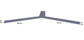 Figure 2-Claw Dimensions
 -
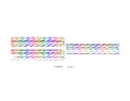 Figure 3-Staple Strands + Plasmid Representation
 -
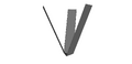 Figure 4-Folded Claw
 -
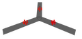 Image:Figure 5-Claw with 5 binding sites
 -
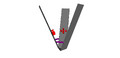 Figure 6-Claw with tethers and 5 binding sites


XXXImproved formation of DNA claw; now ClawX XXX
Our DNA claws have never really given us a nice band on a gel. Claw bands were always rather fat. We figured it was something we had to put up with. Unfortunately, analyzing binding experiments using claws proved to be difficult; we cannot say confidently that a band shift is a shift when the band in question is fat and moves slightly. It may or may not be a shift.
[reference to paper to blunt caps/ends to prevent base stacking]
Inspired by what other groups have done that provided them with tight bands for complex DNA origami systems, we decided to delete from the end structure the staple strands closest to the center of the DNA claw. By leaving these staples out, the synthesized claw should have loops of single-stranded plasmid pointed towards the center.
[link maya image of ClawX?]
These loops of single-stranded DNA should act as a barrier to base stacking seen in DNA to minimize the hydrophobic effect and increase stability. Without these loops, base stacking occurs across two arms of the claw on their centermost sides, warping the claw into the ‘T’ shape often seen in AFM images of our claw. With the loops, base stacking is less likely to occur, leaving the claw in its ideal tri-scalar (double check spelling of this word) configuration. [not triscalar but opened triangular prism (OTP) ]
[maybe illustrative AFM image of old claw and ClawX? Only problem, we don’t really have AFM of clawX]
Comparing these claws, designated ClawX, with the previous version of claw that includes all staples, one can see a clear improvement on band shape, as seen in Image CC2. A now tighter band for claw will allow for more confident analyses to be made regarding binding.
[link Image CC2 (comparison b/w old claw and ClawX); edit image to show what’s what; detailed lanes list?] Should this be in RESULTS???
The logical next step in the project would be to try VLP binding with the ClawX design. As seen in Image CC3, there is a noticeable change from the unbound ClawX to the VLP-bound ClawX, going from tight to much fatter/smeary. Without further imaging (such as AFM and TEM), it cannot be concluded that it is an ideal binding event. However, the drastic change in band shape indicates that some kind of interaction has taken place between the ClawX and the VLPs.
[link Image CC3 (binding with ClawX, B vs S); edit image to show what’s what; detailed lanes list?]
Modified MS2 Virus-Like Particle (VLP)
MS2 VLP (Figure 7) was provided by Berkeley University. It was modified with single stranded regions in order for to facilitate VLP claw binding (Figure 8), where Figure 9 represents T21 sticky ends, complementary to the A21 sticky ends on the claw.
The blunt VLP is ~22nm in diameter, the single stranded T21 region is ~7nm long, adding a total of ~14nm to the diameter of the VLP.
- Representation of VLP and T21 regions are not to scale.
-
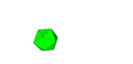 Figure 7-MS2 VLP
 -
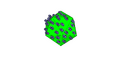 Figure 8-MS2 VLP modified with ‘sticky’ region
 -
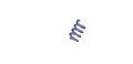 Figure 9-T21 sticky strand


XXXTriangle DOXXX
DO triangle [3] was assembled and modified with A21 sticky ended regions, and trialed as a control experiment in order to illustrate a band shift. (Figure 10) Recently, more modifications were made to the DO triangle. Sticky strands were added in positions that protruded out of the sides of the triangle, and in positions that protruded downwards, towards the direction of the gold surface. Variations of this sticky conformations were assembled.
XXXCadnanoXXX
Cadnano is a tool for designing structures of DNA origami. It was used as a method to systematically represent the origami that we are producing, and to tidily create variations of the origami we were working with. This was used to show the and archive the different formations of both the triangle and the claw. These Cadnano representations are useful in record keeping, and provide a simple way to produce strands for purchase.
Claw
This summer's work on the claw yielded our new "unhinged" claws, which yielded better stability of conformations, and tighter bands in gel electrophoresis analyses. We created Cadnano representations of the original claw and the unhinged claw. These can be seen below.
Triangle
This summer's work on claw involved finding positions that can be used to add sticky ends that will bind to the surface below and positions to protrude out of the triangle, in the same plane as the triangle, whilst maintaining the positions that stick up from the triangle, that will bind to the VLP.
Insert Maya images of strands

