20.109(F14): Mod 2 Day 3 Tools for system engineering
Tools for system engineering
Introduction

The region of the Cph8 protein to focus on for this purpose has been defined through traditional scientific studies of EnvZ, for example the work from Tom Silhavy's lab( PMID: 9721293 and pdf here). We've also been guided by the expertise of MIT's Mike Laub, whose lab studies the specificity and rewiring of two component regulatory systems. From these sources, a short region of the amino acid sequence can be identified as relevant for shifting the balance of EnvZ to greater kinasing or greater phosphatasing activity. The region flanks the histidine (amino acid 243) in EnvZ that is phosphorylated during the signal transduction. In particular A239 and H243 have been shown to enhance the phosphatase activity of EnvZ and mutations in the internal residues (G240 V241 S242) as well as the residue T247 enhance the kinase activity of EnvZ. The amino acid changes that modify the enzymatic activities are indicated on the figure below. Two important notes about these mutations though: First, the balance of kinase to phosphatase activities have been affected by the changes, but the mutations do not shift the reactions to fully "on" or fully "off." Second, the fusion protein of Cph1 to EnvZ, called Cph8, changes the numbering of the residues, as shown in the figure below. It's hoped, however, that the local environment of the region is similar to the natural EnvZ protein. 
To complement the genetic approach for solving biological engineering puzzles, we'll also consider three more approaches in synthetic biology. The first is a Registry of Standard Biological Parts, essentially a community resource that has some ready-made and useful genetic elements that can be assembled into synthetic biological devices systems. The second approach is to recapitulate the genetic network of the biological system using electronic components, making explicit some of the benefits and limitations of such an approach and the often-cited analogy between building with biology and building with computer programs or electronic components. The final approach is the one you started last time, namely the use the Tinkercell computer model to simulate the behavior of the bacterial photography system, with the goal of performing "in silico" experiments that would take days or weeks to do at the bench.
Protocols
Before you leave today, you should examine the bacterial photograph you set up last time and document your work and your ideas about the experiment.
Part 1: Library Screen
The details for how the libraries were constructed and what kinds of changes are reasonable to expect will be considered in the next lab session. For today, you will transform a pool of DNA with degeneracies in the positions that affect the kinasing and phosphatasing activity of EnvZ. The recipient bacterial strain is identical to the bacterial photography system except that it does not harbor a plasmid encoding the light-sensing fusion protein Cph8. It does encode the OmpR-regulated LacZ gene as well as the phycobilins from a plasmid.
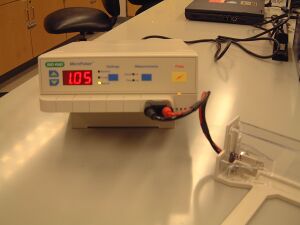
- When you are ready to electroporate the library, retrieve an aliquot of cells from the teaching faculty, a sterile cuvette, and an aliquot of rich, pre-warmed "SOC" media.
- Put the cuvette on ice.
- Pipet 1 ul of the library DNA (library = 0.4 ug/ul) that is being held in an icebucket on the teacher's bench into your aliquot of cells.
- Let the cells and the DNA incubate on ice one minute.
- Transfer 50 ul of the cells (or more if the tube has more volume) to the chilled cuvette and recover it with the blue lid.
- Put on your safety goggles.
- Tap the cuvette on the bench so the cells rest in the bottom of the cuvette.
- With the cuvette's "nub" facing away from you, slide the cuvette into the electroporation chamber. Push the slide into the chamber until the cuvette is between the metal contacts. The lid on the cuvette will seem to block the path but in fact, it doesn't block the slider if you've lined thing up.
- Make sure the electroporator is set to "Ec2"
- Hold the pulse button until you hear a beep. Listen carefully since the beep is not loud.
- Quickly remove the cuvette from the holder and immediately add the 0.5 ml volume of "SOC" media to the cells. Delaying this addition by even 1 minute has been seen to decrease transformation by 3 fold.
- Transfer the cells and the media back to an eppendorf tube and place the tubes on the nutator in the 37° incubator for 1 hour. During this incubation you can work on Parts 2, 3 and 4 of today's protocols.
- Spread 20 ul of the electroporation mix onto a MacLacMUG+Cam34+Amp25+Kan10 petri dishes. Plate 100 ul of the electroporation mix on another MacLacMUG+Cam34+Amp25+Kan10 petri dish. One of these two dilutions should have single, well-isolated colonies to examine next time. Incubate the plates at 37° in the dark until next time.
Part 2: Registry of Standard Biological Parts
What would it take to make DNA serve as a low-level programming language so that a genome is simply a particular program?
- DNA, like software, has an alphabet but with only four letters in the genetic code.
- Since there are proof-reading mechanisms in the "hardware," i.e. in the cell, syntax errors may be less likely to arise than in Python or Perl or C++.
- The code for cellular programs is messy but, honestly, so are computer programs. Subroutines are often dependent on one another (the cell cycle and DNA replication for example) and parts of the program get reused in useful, but complicated and unpredictable ways (seen as cross-talk in signaling pathways for example).
- Genetic code and computer code are both susceptible to viruses that highjack normally benign functions.
The analogy of the DNA as computer code is not perfect. We have to set aside the presumption of an intelligent agent responsible for writing the initial program as well as accept that natural events will change the code over time (evolution leading to genetic variation--the very thing we're trying to harness in the first part of today's lab). And no good tools exist for systematically debugging the genetic code.
What would make genetic code easier to write? One idea is to make it a more “object oriented” language, defining units of known function that could be combined in standard and predictable ways. One effort to facilitate genetic programming can be found at The Registry for Standard Biological Parts. The Registry is a catalog of parts that describe basic biological functions. For example BBa_B0010 is the part number for a transcriptional terminator. The Registry of Standard Biological Parts makes its parts available to interested researchers and engineers, and allows registered users to add and annotate parts.
To familiarize yourself with the Registry, you'll design a protein-generating device for E. coli. This device will consist of at least 3 parts from the Registry: an ORF, a promoter and a ribosome binding site (RBS).
Finding a protein coding part
Try using the "catalog of parts and devices" to search for a part you'd like to use. Start your search in the "protein coding sequences" and then identify one of interest to you and your lab partner.
- What part number have you chosen?
- Follow the link to the data page associated with part. Is anything specified about its use or performance?
Finding a promoter part
Try finding this part from the "well documented parts list" that's here.
- What part number have you chosen? why?
- What can you learn about the regulation of transcription from this part's number? part's name? part's information at the Registry? Remember these are "well documented parts." What would you still like to know about them that you either have to find elsewhere or already know from some other place.
- Follow the link to the data page associated with this part. Is anything specified about its use or performance?
Finding an RBS
To find an RBS you should restrict your search to a set of the Registry's well-characterized ones from Chris Anderson's lab or the community collection, several of which are from Ron Weiss' lab.
- What part number did you choose?
- Can you anticipate the strength of this RBS in your three part construct? Why or why not?
In plain English, what behavior do you expect for your three part construct? You should include this answer in your lab notebook as well as any information you think is relevant about the parts you've chosen to combine.
Assembly
Part of the usefulness of the Registry is that the parts conform (mostly) to a standardized assembly scheme. This scheme enables the same restriction enzymes to be used to physically piece together parts in series. The scheme does not ensure functional assemblies, however. If you have time before your cells are ready today or before the electronics exercise, then you can familiarize yourself with this "BioBrick™ assembly scheme."
Part 3: Modeling biological versus electrical devices
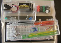
In this section, we'll explore the issue of gain and signal strength in the context of an electrical circuit. As you work through this exercise, consider how the lessons learned from experimenting with an electronic circuit would map to the engineering of biological systems.
Acknowledgements
Many thanks to Tom Knight, Reshma Shetty and Barry Canton who motivated and designed an early version of this exercise. Kudos also to Kelly Drinkwater, BE class of 2011 for her reworking of this material, as well as high school teacher Ralph Peteranderl from Archbishop Williams High School in Braintree High School for his insights and suggestions on the activity.
Safety
- For you: in this exercise, you'll be working with circuits connected to a battery. Although you are unlikely to seriously injure yourself, you should make a habit of unplugging / powering-off the circuit before you touch it.
- For the circuit components: Never directly connect the two battery terminals with wire. This is called a "short circuit" and can damage or drain your battery.
System design
For synthetic biologists, a physical model of a cell may not provide much additional information, but a physical model that illustrates information flow through a genetic circuit might be informative and could be used to make then test predictions about the circuit. As genetic circuits get more complex, modeling the flow of information through them may become impossibly difficult. The bacterial photography system, however, has a reasonably simple logic and so can be used to illustrate the value of a physical model, one that uses electronic components to “stand-in” for the biological ones. In contrast to the bacterial photography system in which the signal is propagated through protein activities, here signals are propagated as either voltage or current. Specifically:
| Electronic Part | Corresponding Component in Living System |
| A momentary switch | Cph8 light sensing system |
| A color generating LED | β-galactosidase + S-gal color reaction |
| Operational Amplifier | The logic that translates OmpR signaling into β-galactosidase activity |
| Battery | Powers the system |
| Wires and resistors | Connect relevant parts and regulates signal flow |
| Breadboard | E. coli chassis |
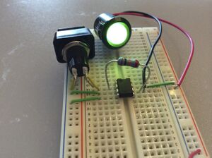
In the electronic system, the switch controls the current entering the circuit and so is analogous to the role played by the membrane-bound light detector protein (Cph8), which detects light and initiates or inhibits a kinasing reaction. The behavior of the light emitting diode (LED) mimics the output of the bacterial photography system by turning on or off depending on the state of the “light detecting” switch component of the circuit. The OpAmp specifies the logic of the system, turning the output off depending on the state of the switch. The OpAmp also models the sensitivity of the system, depending on how much feedback is built into the electronics, as we detail below. Thus, depending on the state of the switch ("on" or "off") and the sensitivity built into the system, the switch generates a current signal. The OpAmp takes in this current signal and produces a voltage, which signals the LED to produce light.
Terminology:
- Momentary Switch: an input sensor. These switches have a small metal spring inside that connects to internal wires depending on whether the button is pressed or not. "Normally off momentary switches" do not complete the circuit until you push on them. The switch is analogous to the Cph8-OmpR signaling system in the living bacterial photography system.
- OpAmp: a signal propagator. More generally, an OpAmp is a logic device that detects and amplifies a difference between the currents into its plus and minus inputs. With the addition of the feedback resistor connecting the output to the minus input, the OpAmp translates an incoming current signal into an outgoing voltage signal. The OpAmp is analogous to the transcription/translation machinery that translates an OmpR signal into synthesis of LacZ in the living bacterial photography system.
- Resistor: component which resists current flow by producing a voltage drop across it. The voltage equals the current times the resistance of the resistor; thus, the resistance sets the "gain" or amplifier strength of the system. By varying the resistance, we can vary the circuit's sensitivity to light. The resistor is analogous to the strength of the promoters and ribosome binding sites in the biological system, which raise or lower the efficiency of LacZ production in the living bacterial photography system.
- LED: a device with a detectable output (analogous to LacZ). A voltage drop across its terminals turns the green-colored light on. The small 820Ω resistor is placed in line with the LED to ensure that the current through the LED isn't too high, which can fry the LED. This small resistor has no direct analogue in the bacterial photography system. The LED is analogous to LacZ in the living bacterial photography system.
- Power: The two terminals of the battery are labeled with a plus (high voltage) and minus (low voltage). When building a circuit, these are also referred to as power and ground, e.g. "To apply voltage across a resistor, connect one end of the resistor to power and the other end to ground."
Introduction to Breadboards
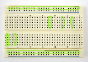
A breadboard is a platform for rapidly prototyping electronic circuits. Inserting wires into the holes in the breadboard’s plastic cover allows users to easily make electronic connections and test multiple circuit configurations. But how do those little holes connect the components together? Let's take a look at the back of a breadboard.
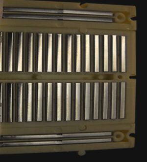
Each of these metal strips on the back of breadboard connects a group of holes that are accessed on the front. Most of the holes are grouped in short rows of five. The holes on the sides, however, are connected in long rows, forming rails that run all the way down each edge of the breadboard. These rails, marked with red or blue lines and plus or minus signs, can be used to conveniently deliver power to many of the 5 hole groups at once. You can connect the power and ground into the rail anywhere along it and, because a metal strip connects the holes, the entire rail then provides either power or grounding when it's connected to a five hole group. Importantly, though, the 5 holes you power are not connected to the 5 holes in the next row, or to the holes on the other side of the groove, or trench, running down the middle of the breadboard.
Lighting an LED
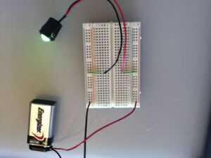
- Power the breadboard by connecting ground from a 9V battery to the blue (-) rail of the breadboard and connecting the plus side of the battery to the red (+) rail on the opposite side of the breadboard
- Run power to the central portions of the breadboard (where the rows with 5 holes are found) using two small wires
- Power the LED
Besides unplugging things, is there a way to turn the light on/off?
Adding a Switch
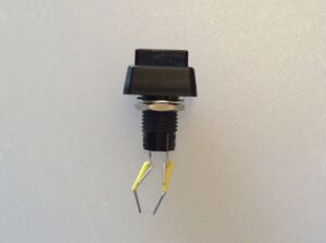
- If it's new, unpack the switch and two small wires from the jumper kit
- Thread the wires through the posts at base of the switch. Connect them so the metal portion of the wires is in direct contact with the metal posts on switch.
- Now add the switch to the circuit so that the LED can be turned on and off. You may need to move the LED leads to a new row of 5 holes or move the wires that power them to make room.
Introduction to OpAmps
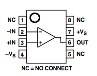
Most electronic components have long bendable wires attached to them. However, the OpAmp, short for "operational amplifier," is a complicated circuit in its own right. It has been packaged inside a little black box with short pins on each side (an integrated circuit). This allows the OpAmp to compare two inputs and then amplify their difference. This conversion occurs over the trench in the breadboard, so that on one side of the trench is the input side for the OpAmp and the other is the output side.
To use the OpAmp, you must position it across the trench in the middle of the breadboard. Each pin gets its own row of holes. The OpAmp has a small circle/divot in the upper left corner of the chip. This marking lets you know which way is up. The circle/divot always marks Pin 1.
OpAmps are very versatile devices. In our case, we will use a feedback resistor between the output and the minus input, which will make the OpAmp act as a current-to-voltage converter.
Building the bacterial photography circuit
A circuit with very tight fully-on-or-fully-off behavior is more "digital", or switch-like, while a circuit where the LED can have a wide middle range of brightness is more "analog", or dial-like. The slope of the output (LED)-vs.-input (switch) line is called the "gain" of the system. A high-gain amplifier will cause the LED's brightness to max out even at a low level of input, whereas a low-gain amplifier will cause the LED's brightness to increase slowly before maxing out, as the input signal increases. The switch we are using is digital so can't be "tuned," but we can modulate the gain in our circuit by changing the value of the gain resistor across the OpAmp. In this next part of your electronics activity, you'll modify the resistance, ranging from infinite resistance in air to zero resistance with a wire running between the input and output.
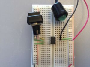
- Power the breadboard as you did when you lit the LED
- Note the small dot or half-circle marking pin 1 or the "top" of the OpAmp and position an OpAmp across the trench. Use wires to connect pins 3 and 4 to ground and pin 7 to power. Use the schematic for the OpAmp that is shown above to confirm that you are connecting the pins to power correctly.
- Connect the switch to ground and to the OpAmp's minus input (pin 2).
- Connect the LED to the power and to the OpAmp's output (pin 6). Does the LED light?
You will change the gain of the amplifier by varying the resistance at this point (using the large resistor, a wire for zero resistance, and no wire for infinite resistance).
- Stretch a wire over the OpAmp to connect the OpAmp's output (pin 6) to the OpAmp's minus input (pin 2). Now does the LED turn on and off with the switch?
- Finally, remove the wire you just added, and connect the OpAmp's output (pin 6) to the 20 Kohm resistor. Connect the other end of the resistor to the OpAmp's minus input (pin 2). This will change the gain of the amplifier again. Does the LED turn on/off with the switch? Use the behavior you’ve observed in this electronic model to think about the genetic circuitry and the flow of information through it
Some questions to ask yourself
Try to put it all together by asking:
- Which part of the biological circuit does each electronic component represent?
- No doubt, building this circuit was quicker and easier than actually assembling a biological circuit -- for example, you didn't have to wait for bacteria to grow, or spend time cutting and pasting wires the way you would cut and paste DNA to make a functional plasmid. What are some traits of these components, of the breadboard, or of electronics in general, that make electrical engineering easy in this way?
- Every analogy has limitations. What are the limitations of the circuit you built as a model of the bacterial photography system? What could you do to make it more realistic?
- How does this activity compare to the end of the computer simulation exercise, when you tuned the system with sliders?
- When might you want switch-like behavior in a biological system, and when might you want dial-like behavior?
- What are some everyday examples of switch-like and dial-like systems? What element or aspect plays the role of "gain" in each one?
Part 4: CAD tool for synthetic biology
If you have time and would like to revisit Tinkercell, you can run additional simulations or gather more information about the system you're experimenting with.
DONE!
For Next Week (Due M2D5)
You should prepare an outline for the introduction to the research article that you will write to describe your work in this experimental module. Your outline should include references that you have found to describe the system and your tuning of it. At this point the references can be in any format you choose. General guidelines for writing up your research can be found here.
- EXTRA CREDIT: you can get 2 points of extra credit on this FNW assignment by doing 2 small things in addition to your outline:
- visit the BE writing lab with your outline to get feedback
- summarize in no more than 5 sentences or bullet points the feedback you were given and how/if you'll address the feedback
NOTE
If you are giving a journal club talk on M2D4,then the slides for your presentation must be uploaded to the Stellar website that is associated with our class. The presentation order will be determined by the order that your finished slides are uploaded.
Reagents
- for electroporation
- Strain NB462 (genotype: MC4100 ara+ Φ(OmpC-lacZ) 10-25 ΔenvZ::KanR +pPL-PCBamp)
- pCph8 library (0.4 ug/ul): see Day 5
- SOC media
- 0.5% Yeast Extract
- 2% Tryptone
- 10 mM NaCl
- 2.5 mM KCl
- 10 mM MgCl2
- 10 mM MgSO4
- 20 mM Glucose
- Mac(Lac)MUG (Sigma cat#63014)+ Amp + Cam plates
- 50.1 grams MacConkey Lactose MUG Agar per liter
- 25 ug/ml ampicillin (final concentration)
- 34 ug/ml chloramphenicol (final concentration)
| Part | Catalog # | ~Cost |
| Breadboard | 64 | 5 |
| 9V snap battery cover | 090-805 | 0.25 |
| 9V battery | anywhere | 1.5 |
| LED | B4383H5 - Chicago Miniature / IDI | 4 |
| Resistor, 20 Kohm | QW182, 820 ohm, 2% | 1 |
| OpAmp | LM741CNJP-6pk | 5 |
| momentary switch | 54-390 NTE | 5 |
| Wires | JW-70 | 10 |
| Resistor color code card | CC-100 | 1 |
| Clear case to hold parts | DB221 | 2 |
Navigation Links
Next Day: Mod 2 Day 4: Journal Club I Previous Day: Mod 2 Day 2: Measuring system performance
