Laminar Flow - Marco Zaky Elizabeth Swanson and Jay Mistri
Laminar Flow

Laminar flow is fluid flow characterized by parallel lines flowing linearly with little to no mixing. In laminar flow, no mixing occurs and is seen as very orderly flow. Specifically, flow is determined to be laminar at low Reynolds numbers (Re). The Reynolds number can be calculated with the following equation:
[math]\displaystyle{ \mathrm{Re} = \frac{ \mbox{inertial forces} }{ \mbox{viscous forces} } = \frac{\rho v D}{\mu} }[/math]
where:
- [math]\displaystyle{ \rho }[/math] is the density of the fluid
- v is the average velocity of the fluid
- D is the diameter of the channel
- [math]\displaystyle{ \mu }[/math] is the viscosity of the fluid
More information can be seen on the next page Reynolds Number - Blayne Sarazin
Laminar Flow In Microfluidics
Fluid flow within microfluidic channels is laminar since it is typically characterized by low Reynolds numbers. The numerator of the Reynolds number is very small due to the channels having dimensions in ranging from nano to millimeters while the denominator, viscosity, remains constant for most fluids (Newtonian Fluids) and both are not manipulable. The velocity of the fluid then is the only variable capable of inducing turbulent, or mixing, flow yet the microfluidic devices are often not capable of handing the pressure produced by the high velocities. Thus, turbulent flow is difficult to produce at micro scale systems and elaborate mixing systems must be implemented in order to mix fluids. Velocity remains as the variable that is most easily manipulable, since the channel dimensions are often predetermined in order to represent the micro-scale environments as well as the fluid to be tested.
Flow Profile
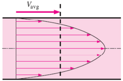
Laminar flow is depicted in figures as straight parallel lines, which is known as the flow profile. The flow profile changes slightly based off of the channel dimensions, fluids used, as well as possible motion of the channel walls.
Parabolic Flow
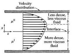
Parabolic Flow is the most commonly viewed flow profile for channels, seen in Figure 2. The flow profile is depicted as a parabola with a velocity of zero at the wall and an increase in fluid velocity nearer to the center of the channel. The fluid velocity decreases closer to the stationary walls due to drag.1,6 Channels with multiple fluids, seen in Figure 3, also exhibit parabolic flow yet each fluid has its own parabolic profile differing in shape due to differences in each fluid's physical characteristics such as viscosity.
Moving Walls
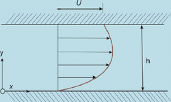
Fluid flowing within a chamber with the addition of the walls also moving creates interesting flow profiles. While this system may not be applicable to microfluidics, it does represent how the flow of two liquids would act when in contact with one another, visible when comparing Figure 3 to Figure 5.
Stokes Flow
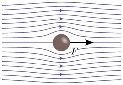
Stokes flow, also referred to as creeping flow, is a type of laminar flow with a Reynolds number less than 1.7 An example of Stokes flow can be seen in Figure 4, where from the flow lines it can be seen that the fluid flows around the ball without crossing other flow lines, or mixing, or leave any eddies in its wake.
Examples in Microfluidics Utilizing Laminar Flow
Microfluidic devices have a very small tube diameter (<1 cm) which results in a lower Reynolds number. This allows the fluid flow to be laminar even at higher velocities, making processes faster. Because layers are not disrupted in laminar flow, microfluidic devices can control particular separations or mixing at desired points. Separating out components of a mixture using a gradient or a charge will allow the laminar flow to continue undisturbed throughout the device. For example, hydrodynamic lift is used to sort cells in a red blood flow [3].
Microfluidic Fuel Cell
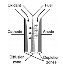
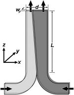
Microfluidics can be used to create small, portable fuel cells that can be used to power common appliances such as phones and laptops. Developing microfluidic fuel cells takes advantage of the multi-stream laminar flow in a microscale system [10]. This is done to separate fuel streams from mixing with oxidant streams while still keeping them in contact. The system is composed of a Y-shaped channel that allows fuel and oxidants streams to flow parallel to each other between two catalyst-coated electrodes as shown in Figure 6.
Air-Breathing Laminar Flow-Based Microfluidic Fuel Cell
An upgraded design made this more utilized. Previous design was what is called cathode-limited because of insufficient solubility and slow movement of the oxygen in liquid solutions. Newer designs allow a higher concentration of oxygen flow through the device. With this new design these Air breathing Laminar Flow-Based Microfluidic Fuel Cell has the potential to fabricate and improve the chemical composition of the cathode11. In turn, this could greatly improve the electrode performance and fuel utilization. This could be utilized to get rid of pollution caused by burning fossil fuels.
Spatially Selective Manipulation of Supported Lipid Bilayers
Laminar flow can be used to remove, study, and experiment with lipid bilayers, essential features in the structure and regulation of living cells. A stream of a detergent solution can be used to remove the lipid bilayer through diffusion limited mixing, which can only be done with a laminar flow [12]. Application of this detergent solution through flow at very low Reynolds numbers can remove the lipid bilayer within micrometers of precision and the resulting exposed surface will form a new bilayer upon exposure to new lipid vesicles.
Theoretical Analysis of Molecular Diffusion
A device called a T-sensor that operates at low Reynolds numbers to make sure it is run by laminar flow, meaning that transport between streams only occur via diffusion. Two fluids are input on a side-by-side configuration. Because this is pressure driven, the velocity profile of this device will be parabolic. This device, T-sensor, can be used to measure diffusion coefficients. Initially, it was used as a diagnostic device for chemical assays.
Extraction for Bovine Serum Albumin (BSA) in a Simple Coaxial Capillary Microfluidic Device
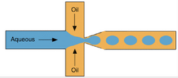
Using a microfluidic based separation via mass transfer, we can separate bovine serum albumin (BSA) in a two-phase extraction manner. Using the Bradford method, we can figure out the protein concentrations of BSA. This device used polyethylene glycol and ammonium sulfate as the aqueous solutions. After, the correct flow rates were determined. If need be, the mass transfer area and time can be controlled with the change of the said flow rate. At a rate of 1.2 seconds per extraction cycle in a coaxial microfluidic device, the BSA recovery yield is over 71%. Very much higher than current beaker aqueous bi-phase separation processes. As you can see, challenging tasks such as measuring diffusivity can be done, but laminar flow devices can also be used for more common everyday measurements.
Pressure-Driven Laminar Flow in a Tangential Micro-channel
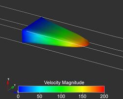
With the use of two microfluidic channels made in layers that contact each other on a face-to-face configuration, (90 degree angle) with fluid flowing in a perpendicular regime, we can describe laminar fluid flow through a 3-D elastomeric microstructure. There are a couple ways to control fluid flow through the said channels. The first way to control these tangentially connected channels, is by applying an outside force or pressure and changing the aspect ratio of the channels. The second way to control this laminar fluid flow is to inject additional streams of fluid into said channel.
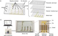
Analysis of Fully On-Chip Microfluidic Electrochemical Systems
Relying on a low Reynolds number flow to keep good separation of the working electrode and counter electrode. Two coupled working electrode and counter electrode were placed in a parallel regime along the axial flow direction. The potential drop for the facing working electrode and counter electrode was found to be non-significant due to an experimental examination of an on-chip integrated reference electrode. The utilization of a quasi-reversible probe the diffusion limited voltametric current was different from what the Levich equation suggested when neglecting the horizontal diffusion. This is believed to be a result of a high ratio of mass transfer to kinetics when comparing it to a microfluidic device vs the disk electrode. However, in compliance with the Levich equation, the lateral diffusion was able to make up for the current distortion. Seeing how this was able to occur, the Koutecky-Levich method was used for the analysis of fully on-chip microfluidic electrochemical systems under laminar flow.
References
- Bird, R. Byron, Warren E. Stewart, and Edwin N. Lightfoot. Transport phenomena. John Wiley & Sons, 2007.
- Sun, M. H., et al. "Characterization of microfluidic fuel cell based on multiple laminar flow." Microelectronic Engineering 84.5 (2007): 1182-1185. http://dx.doi.org/10.1016/j.mee.2007.01.175
- Huang, Y., Meng, T., Guo, T. et al. Microfluid Nanofluid (2014) 16: 483. doi:10.1007/s10404-013-1245-2 http://dx.doi.org/10.1021/ac010374q
- Huang, Yushi, et al. "Aqueous two-phase extraction for bovine serum albumin (BSA) with co-laminar flow in a simple coaxial capillary microfluidic device." Microfluidics and nanofluidics 16.3 (2014): 483-491. http://dx.doi.org/10.1007/s10404-013-1245-2
- Li, Yan, et al. "Analysis of Fully On-Chip Microfluidic Electrochemical Systems under Laminar Flow." Electrochimica Acta (2017). http://dx.doi.org/10.1016/j.electacta.2017.02.054
- Nave, R. (2005). "Laminar Flow". HyperPhysics. Georgia State University. Retrieved 23 November 2010. http://hyperphysics.phy-astr.gsu.edu/hbase/pfric.html
- Kim, S. & Karrila, S. J. (2005) Microhydrodynamics: Principles and Selected Applications, Dover. ISBN 0-486-44219-5.
- Geislinger, T. M.; Franke, T. Hydrodynamic lift of vesicles and red blood cells in flow — from Fåhræus & Lindqvist to microfluidic cell sorting. Advances in Colloid and Interface Science 2014, 208, 161-176. http://dx.doi.org/10.1016/j.cis.2014.03.002
- Salafi, T.; - Zeming, K. K.; - Zhang, Y. - Advancements in microfluidics for nanoparticle separation. - Lab Chip. http://dx.doi.org/https://doi.org/10.1039/c6lc01045h
- Choban, E. R.; Markoski, L. J.; Wieckowski, A.; Kenis, P. J. Microfluidic fuel cell based on laminar flow. J. Power Sources 2004, 128, 54-60. https://doi.org/10.1016/j.jpowsour.2003.11.052
- Air-Breathing Laminar Flow-Based Microfluidic Fuel Cell Ranga S. Jayashree,†, Lajos Gancs,‡, Eric R. Choban,†,‡, Alex Primak,§, Dilip Natarajan,§, Larry J. Markoski,*,§ and, and Paul J. A. Kenis*,†,‡ Journal of the American Chemical Society 2005 127 (48), 16758-16759 https://pubs.acs.org/doi/full/10.1021/ja054599k
- Kam, L.; Boxer, S. G. Spatially selective manipulation of supported lipid bilayers by laminar flow: steps toward biomembrane microfluidics. Langmuir 2003, 19, 1624-1631. https://dx.doi.org/10.1021/la0263413
- Kamholz, Andrew Evan, and Paul Yager. “Theoretical Analysis of Molecular Diffusion in Pressure-Driven Laminar Flow in Microfluidic Channels.” NeuroImage, Academic Press, 6 Jan. 2009. https://www.sciencedirect.com/science/article/pii/S0006349501760031
- Schilling, Eric. “Basic Microfluidic Concepts.” Basic Microfluidic Concepts. http://faculty.washington.edu/yagerp/microfluidicstutorial/basicconcepts/basicconcepts.htm.
- Lignos, Ioannis G., et al. “Segmented Flow Microfluidics.” SpringerLink, Springer, Berlin, Heidelberg, 1 Jan. 1970. http://link.springer.com/10.1007/978-3-642-16712-6_721.
- Lee, GeonHui, et al. “Single Microfluidic Electrochemical Sensor System for Simultaneous Multi-Pulmonary Hypertension Biomarker Analyses.” Nature News, Nature Publishing Group, 8 Aug. 2017. http://www.nature.com/articles/s41598-017-06144-9.
