Biomolecular Breadboards:Protocols:Cycle Time Measurements
| Home | Protocols | DNA parts | Preliminary Data | Models | More Info |
Design cycle time analysis: Testing simple circuits on the cell-free breadboard
Creating a functioning biocircuit can be a lengthy process, involving multiple iterations of design, assembly, and testing. As such, there is general interest in finding methods to do this faster. The cell-free circuit breadboard is an ideal testing platform which takes advantage of shorter assembly and troubleshooting times by conducting reactions in vitro. With the breadboard, circuits can be prototyped using multiple plasmids or linear DNA, as requirements for propagating plasmids in vivo have been removed. This results in faster design times and quicker iterations of the design, assembly, and testing process. An in vitro platform also enables precise control of DNA concentration and expression of toxic constructs, both of which are challenging in vivo.
To demonstrate assembly-to-testing times in the cell-free circuit breadboard, we have chosen two circuits: the negatively autoregulated gene, and the bistable toggle switch. The first test of the negatively autoregulated gene in the TXTL system took 6.5 hours from start of assembly to testing phase. The more complicated bistable switch was run on a system of 4 plasmids in 3 days.
| Circuit | Assembly time | |||
|---|---|---|---|---|
| In vitro testing (linear DNA) |
In vitro testing (multiple plasmids) |
In vitro testing (single plasmid) |
In vivo testing (single plasmid) | |
| Negatively autoregulated gene | 6.5 hours | N/A | 3 days | 3 days* |
| Bistable switch | 6.5 hours* | 3 days | 5 days* | 5+ days* |
* Estimated time based on similar constructions. All other times are measured.
Negatively Autoregulated Gene
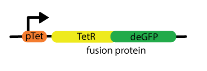
We tested a simple 3-component circuit, consisting of the pTet promoter in front of a TetR-deGFP fusion protein. The circuit functions as a negative feedback loop, with its product repressing its own production. It was first constructed by Becskei, J & Serrano, L. (2000)1 and again described by Rosenfeld, N., Elowitz, M.B. & Alon, U. (2002)2.
| Figure 1. To the left, the linear form of the circuit, as tested in TXTL. To the right, the 4 components used to create it: a plasmid backbone (pBEST plasmid), the promoter pTet, the TetR repressor and the deGFP reporter protein. To fuse TetR and deGFP, Gibson3 primers were designed to code for a linker, parts registry BBa_I717014. |
1) Fastest method - same day testing with linear DNA
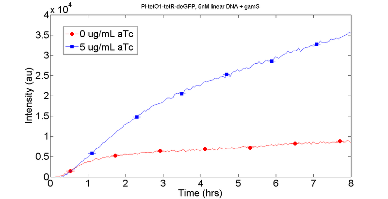
Designing the circuit and ordering the primers took one day. We received the primers at noon the day after ordering, and started assembly immediately. For both the negatively autoregulated gene and the bistable switch, there was no wait time for parts as we used DNA components from plasmids we already had in lab. To create the circuit, we used PCR to amplify 4 components, each from a different plasmid. We ran a gel to check the success of the PCR, and then PCR purified the product. We then assembled the products with Gibson assembly. Traditionally, for in vivo testing the Gibson product is transformed into competent cells and plated for overnight growth. However, since we can run linear DNA in vitro the Gibson product can also be PCR-amplified as a template. After another gel to check for success, we PCR purified the product and ran the circuit 8 hours in TXTL. The results of the linear DNA run is shown below to the right. GamS, an inhibitor of the RecBCD complex, was added to the sample to prevent linear DNA degradation.
Figure 2. To the left: the time breakdown of the construction of the negatively autoregulated gene, from assembly to cell-free circuit breadboard. To the right: the results of a cell-free breadboard run with linear DNA that was PCR amplified off Gibson assembly product. Linear DNA at a concentration of 5 nM was run with gamS and both with and without the addition of 5 ug/mL anhydrotetracycline (aTc), a tetracycline analog that acts as an inducer by binding to and inhibiting the repressor protein TetR.
2) Three days to testing, standard plasmid circuit
To test if the results from the cell-free breadboard run of the linear negatively autoregulated gene (Figure 2) were an accurate gauge of the performance of the circuit in plasmid form, we also transformed and plated the Gibson product into competent cells. The transformed bacteria were then incubated overnight, and colonies were screened by colony PCR to test for successful Gibson assembly. Colonies that contained the correct insert were then grown up in liquid cultures overnight. The next day, the plasmids were extracted with a plasmid purification kit, and then cleaned up with a PCR clean-up kit. Total assembly time took 3 days.
| Day 1 | Day 2 | Day 3 | ||||||||||||||||||||||||||||||||||
|
|
|
Figure 3. Time breakdown of the construction of the negatively autoregulated gene on one plasmid, from assembly to testing on the cell-free circuit breadboard. Circuit assembly took 3 days, with the cell-free breadboard run on the third day and results gathered that same evening.
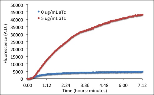
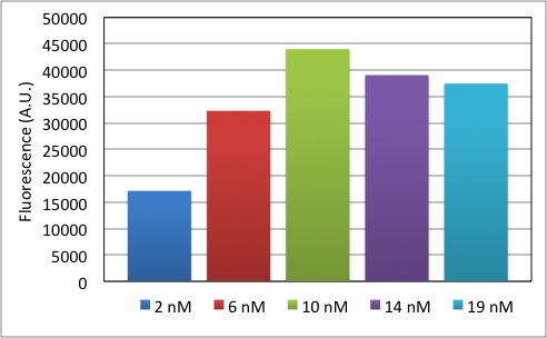
Figure 4. A plasmid encoding the negatively autoregulated switch, run in the cell-free circuit breadboard. To the left: 10 nM of plasmid, run with and without 5 ug/mL of inducer aTc. To the right: endpoint fluorescence at 8 hours of 2 nM - 19 nM of plasmid, with 5 ug/mL aTc. The ability in the cell-free circuit breadboard to vary the amount of plasmid added to the system permits the exploration of the effects of plasmid concentration on circuit function. Here, as the plasmid concentration initially increases, so does signal. However, at high concentrations of DNA eGFP signal decreases, which we believe is due to inducer sequesteration by TetR but can be further explored with inducer assays.
Bistable Toggle Switch
The bistable switch was initially constructed by Gardner, T.S., Cantor, C.R. & Collins, J.J. (2000)4. PTet drives LacI production and a reporter, while pLac promotes TetR and another reporter. Due to the nature of the switch, only pTet or pLac can be on at one time, since each represses the other. pTet can be turned on by the addition of IPTG (Isopropyl β-D-1-thiogalactopyranoside), an allolactose analog, and pLac by the addition of aTc.
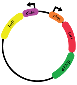
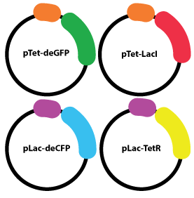
Figure 5. To the left: the bistable toggle switch, on a single plasmid. The construction parallels that in Gardner, Cantor & Collins (2000), but with an additional reporter. In the middle: The four plasmid system we used to test the bistable toggle switch. Each plasmid has one promoter-gene pair. To the right, the linearized form of the bistable switch. Assembly of circuits on linear DNA can cut down traditional assembly times, by removing steps necessary for plasmid assembly such as tranformation, plating, and/or miniculture.
1) Estimated minimum five days to testing, standard plasmid circuit
Constructing the entire bistable switch on one plasmid would require the assembly of at least six different parts. Below, we've calculated the estimated time needed to construct such a circuit, using a standard method of multi-part DNA assembly, Gibson assembly. At least two different rounds of Gibson assembly would be required, making the time needed at least 5 days. This is the same time recently recorded for the assembly of the bistable toggle in Litcofsky, K.D. et al Nature Methods5.
| Day 1 | Day 2 | Day 3 | ||||||||||||||||||||||||||||||||||||||
|
|
| ||||||||||||||||||||||||||||||||||||||
| Day 4 | Day 5 | |||||||||||||||||||||||||||||||||||||||
|
|
Figure 6. Calculated breakdown of the time needed to construct the bistable switch on one plasmid, using 2 rounds of Gibson assembly. Estimated minimum 5 day total assembly time.
2) Three days to testing, 4 plasmid circuit
Instead of constructing the bistable switch through one plasmid as described above, we took advantage of the lack of living bacteria in our testing platform. Bacteria can only carry limited plasmids, limiting circuits designed for in vivo testing. However, in vitro testing has no such limitation, making circuit design more flexible. We chose to assemble the bistable switch onto 4 plasmids, each with one translational unit (a promoter-gene pair). This method required only one round of Gibson assembly per plasmid, cutting construction time down to 3 days. Additionally, having components spread over 4 plasmids reduced design times when troubleshooting, since swapping out parts only required redesign and assembly of a 2 component plasmid, instead of the 5 component assembly that would have been necessary for a one plasmid system.
The time breakdown for the bistable switch assembly is shown in Figure 3, as it mirrors the construction of the plasmid for the negatively autoregulated gene. Although there were 4 plasmids to be assembled, their assemblies are done in parallel, so the increase in number of plasmids from 1 to 4 did not affect the assembly time.
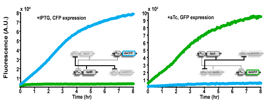
Figure 7. "Switching" behavior of the 4 plasmid bistable toggle system, run on the cell-free circuit breadboard. To aid in visualization of the circuit's "switching," one of our 4 plasmids contains a second reporter protein, CFP, placed behind the pLac promoter. On the left, 500 uM of IPTG has been added to the sample, and CFP is turned on while GFP is turned off. On the right, 5 ug/mL of aTc has been added instead, and GFP is on while CFP is off. All plasmids are at 2 nM concentration.
3) Two days to testing, Linear DNA
As demonstrated in section 1 of the negatively autoregulated gene, above, it is possible to test constructs in just one day, by PCR amplifying Gibson assembly product and running the cleaned PCR products in the cell-free circuit breadboard. Another shortcut, which also takes advantage of the ability to use linear DNA in the TXTL reaction, is to use the product of the colony PCR for testing. Normally, colony PCR is a diagnostic test, used to determine which colonies took up the correct Gibson assembly product. However, the PCR products can also be purified and run in the breadboard.
| Day 1 | Day 2 | |||||||||||||||||||||||||||||
|
|
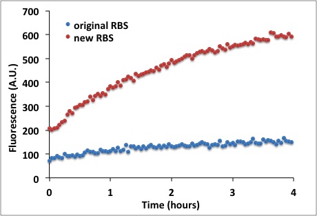
Figure 8. To the left: the time breakdown to construct a linearized component of the bistable switch, the pTet-deGFP translational unit. The same breakdown and total time would apply when using this method to construct the whole switch, in linearized form. The reduction of a day in assembly time from plasmid to linear comes from not having to grow the overnight miniculture. To the right: when experimenting with different ribosomal binding sites (RBS) for the pTet-deGFP plasmid, we used the products from colony PCR to test whether the new RBS was stronger than the previous. Linear DNA encoding pTet-deGFP with the previous RBS was run at 10 nM against the PCR product with the new RBS, also at 10 nM. Atc was present at 5 ug/mL. GamS, an inhibitor of the RecBCD complex, was added to the sample to prevent linear DNA degradation.
1. Becskei, A. & Serrano, L. (2000). Engineering stability in gene networks by autoregulation. Nature, 405, 590 – 593.
2. Rosenfeld, N., Elowitz, M.B. & Alon, U. (2002). Negative autoregulation speeds the response times of transcription networks. J. Mol. Biol., 323, 785–793.
3. Gibson, D.G. et al. (2009). Enzymatic assembly of DNA molecules up to several hundred kilobases. Nature Methods, 6(5): 343–345.
4. Gardner, T. S., Cantor, C. R. & Collins, J. J. (2000). Construction of a genetic toggle switch in Escherichia coli. Nature, 403, 339–342.
5. Litcofsky, K.D. et al. (2012). Iterative plug-and-play methodology for constructing and modifying synthetic gene networks. Nature Methods, Advanced Online Communication.
6. Geneious® Pro 5.6.4 created by Biomatters.
