Biomolecular Breadboards:Preliminary Data
| Home | Protocols | DNA parts | Preliminary Data | Models | More Info |
This page contains some data that we have taken with the TX-TL breadboard.
Plasmid Expression of GFP
Using pBEST-OR2-OR1-Pr-UTR1-deGFP-T500, a plasmid enhanced for GFP expression, the biomolecular breadboard is able to express mass at equal concentrations to comparable bacteriophage in-vitro systems (J. Shin and V. Noireaux, 2010).
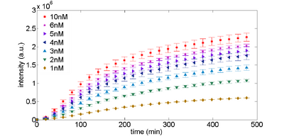
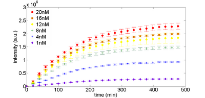
Expression of plasmids can be optimized by concentration. Figure 1 (below) shows a typical time response for expression of the control plasmid, along with the data we collected from our plate reader. If you are trying to get TX-TL working, this is probably the first test that you should do.
Figure 1. eGFP expression as a function of plasmid DNA template. Plasmid DNA pBEST-OR2-OR1-Pr-UTR1-eGFP-T500 is varied by concentration. |
Protecting Linear DNA from Exonuclease-Mediated Degradation
Current standards for circuit design utilize plasmids for DNA template, which require time-consuming subcloning steps. However, circuits based on linear DNA require only PCR assembly or gene synthesis, which drastically decreases preparation time. As a purely extract-derived system, our biomolecular breadboard exhibits exonuclease activity which degrades linear DNA. We are developing multiple technologies to protect linear DNA from exonuclease degradation. These include:
- Protecting linear DNA using noncoding segments
- Inhibiting RecBCD exonuclease with gamS
- Adding thiosulfate bonds to 5' ends
Protection Sequences
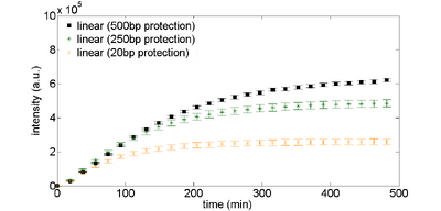
The simplest way to protect linear DNA is to put additional "junk" DNA around the construct you are testing. Figure 2 shows the expression curves for different lengths of protection sequences. The overall expression with long protection sequences is about 2X less than what you see with plasmid DNA (compare the plots below to the 2nM plasmid DNA expression levels in Figure 1).
GamS
This plasmid is now available through Addgene: https://www.addgene.org/45833/
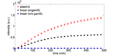
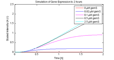
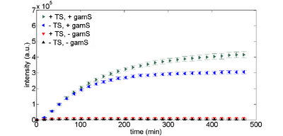
The GamS protein can be used to protect linear DNA. GamS is a shortened version of the lambda phage Gam protein, which inhibits activity of the exonuclease RecBCD (Murphy, 2007). Figures 3 and 4 show time responses for expression of linear DNA using GamS. Using a combination of GamS and protection sequences, it is possible to get approximately 60% of the expression that you get from plasmid DNA.
|
|
Note that you can include GamS in your reactions either by putting in the DNA encoding GamS or by supplying purified GamS into the reaction. We recommend the latter since using DNA to express GamS uses up some of the resources that would otherwise power your circuit, and also takes a while before you express enough GamS to protect linear DNA.
Thiosulfate Bonds
We have also tried using thiosulfate bonds to protect linear DNA. These have little effect.
Protein Degradation
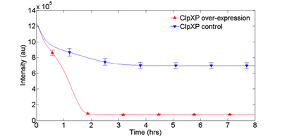
Implementing protein degradation is integral to enabling the function of many dynamical circuits, such as oscillators or feed-forward loops. We have been exploring the overexpression of AAA ATPases ClpXP to selectively target proteins with degradation tags. Initial experiments indicate that ClpXP, when overexpressed, can accelerate degradation of purified eGFP-ssrA (Fig. 1). We will further characterize this AAA ATPase family, as well as try to demonstrate its use through an incoherent feed-forward loop. We have not been able to replicate the results by adding purified ClpXP protein. However, we intend to express ClpXP off of plasmids or to create custom extract with ClpXP already overexpressed to enable rapid protein degradation.
Environmental Context
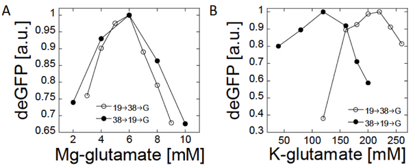
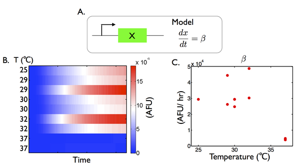
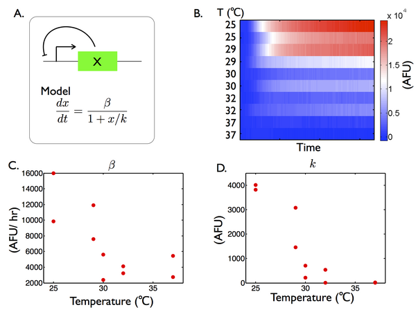
The TX-TL system can be used to study the operation of circuits in different environmental contexts, including salts, energy levels and temperature.
Magnesium and Potassium concentration
|
|
Toxicity
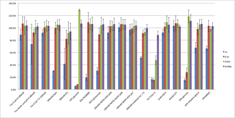
To optimize TX-TL for the addition of proteins of interest or reagents (such as gamS for linear protection and ClpX for protein degradation), a toxicity assay was preformed for multiple commonly used additives. The results of the toxicity assay demonstrate that while salt additives and pH modifications do not significantly affect TX-TL efficiency, solution viscosity and detergent are large factors. In specific, the common cryoprotectant glycerol is sub-optimal. Based on this information, new protein buffers were designed with optimal salt content and DMSO as a cryoprotectant in place of glycerol.
Figure 1: Effects of different additives on TX-TL efficiency. A variety of different additives commonly used in protein buffers was tested for toxicity. 25% of the reactions containing the above additive was added to 1nM pBEST-Or2-Or1-Pr-UTR1-deGFP-T500 and endpoint fluorescence after 8 hours was determined – percentages are against a control with no additive internal to the experiment. Error bars represent one standard deviation from three independent experiments.
Temperature
|
|
|
|
Characterizing early time "Dip" in TX-TL curves. (CSHL SynBio 2014)
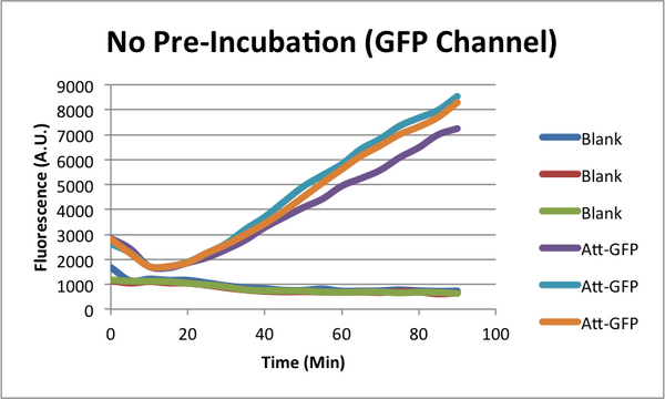
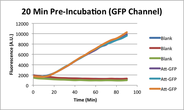
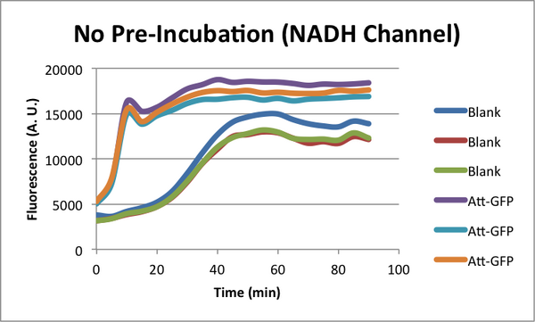
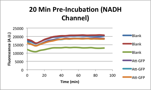
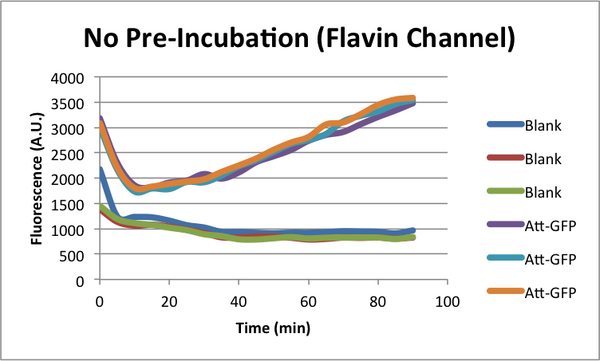
When monitoring GFP expression in TX-TL reactions, there is often a 'dip' in fluorescence in early times. In addition, there appears to be a 'lag time' for TX-TL gene expression reactions over the first 10-20 minutes which could also be a part of this dip phenomena. CSHL SynBio 2014 is doing some experiments to characterize this dip and come up with solutions to get rid of it.
Experimental Design
* 2 Conditions in each TX-TL run: blank (no template), and Att-GFP (expresses GFP)
* 2 types of runs: one with a 37C pre-incubation of the extract for 20 minutes, one with no pre-incubation
Biotek H1 Settings:
* Read 1 = GFP
* Read 2 = Flavins
* Read 3 = NADH
Plate Type 384 WELL PLATE Set Temperature Setpoint 37°C Preheat before moving to next step Start Kinetic Runtime 1:40:00 (HH:MM:SS), Interval 0:05:00, 21 Reads Read Fluorescence Endpoint A1..A12 Filter Set 1 Excitation: 485, Emission: 520 Optics: Bottom, Gain: 100 Filter Set 2 Excitation: 450, Emission: 540 Optics: Bottom, Gain: 100 Light Source: Xenon Flash, Lamp Energy: High Read Speed: Normal, Delay: 100 msec, Measurements/Data Point: 10 Read Height: 9.5 mm Read Fluorescence Endpoint A1..A12 Filter Set 1 Excitation: 350, Emission: 460 Optics: Bottom, Gain: 100 Light Source: Xenon Flash, Lamp Energy: High Read Speed: Normal, Delay: 100 msec, Measurements/Data Point: 10 Read Height: 9.5 mm End Kinetic
Data Analysis
Curves represent raw data (no background subtraction).
GFP Characterization
|
|
|
|
NADH Characterization
|
|
|
|
Flavin Characterization
|
|
|
|
