Biomod/2015/StJohns:Design
http://openwetware.org/images/f/f9/Lukemanlab-toehold-conga-nanny-header.jpg
Design
Claw
In the assembly of our generic claw M13mp18 plasmid is used as a scaffold. This scaffold then is folded into the ‘Claw’ structure (Figure 2). There are 226 staple strands, which hold this structure together; the location of each can be pinpointed using the coordinates shown (Figure 3). Removing one of the original staple strands, and inserting another in which the sequence is only partially complementary to the region can create a sticky region. Taking into account the helical twist of DNA folding the positioning of the sticky end of the staple strand is crucial. The design of this Claw requires that the sticky ended region be an A21 series. Vanilla 'sticky' and 'blunt' claws were designed.
The design of NClaw required several of the original staple strands to removed in order to insert one donor and two acceptor sites for FRET (Fluorescence Resonance Electron Transfer) analysis. These sites were placed close to the hinged portion of the claw, allowing them to be close enough to visualize an energy transfer upon the closing of the claw. As a result when imaging the claw in an unbound position (Figure 2), there would be less energy at the acceptor sites, when compared to the closed [or bound] position (Figure 4). The donor and acceptor sites are closer together and thus are able to transfer and accept a greater energy transfer.
The original design of the Vanilla Claw and NClaw contained one binding site per arm, making a total of 3 for the entire claw. After not witnessing capsid-claw binding, via gel shift, it was decided that adding several binding sites/arm might increase the likelihood of the capsid successfully attaching, Experiments were carried out using two versions of 3 three binding sites, one in which the binding sites created a horizontal-facing triangle (<) and (>), the other in which the triangle was vertical (^), 4 binding sites, and 5 binding sites (Figure 5). It was decided that using 5 binding sites allowed the capsid to bind with greater avidity (See Figure 14 in Results). At this point 5S Claw was created, indicating 5 binding sites on sticky claw.
The latest version of the claw includes the addition of tether strands (TClaw: Figure 6). This was done in order to limit the mobility of each of the claw arms, once again in hopes of increasing the efficiency of capsid-claw binding and minimizing the apparent polymerization we observed in all claw-capsid binding events. The tether strands were attached 20nm from the hinges of the claw, taking into consideration the location of the sticky ends, located at 55nm from the hinges of the claw. This gave just about enough space for the tethers to be placed in a location where they will not hinder the capsid binding. Tether lengths were varied from 21-49nm.
-
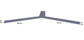 Figure 2-Claw Dimensions
 -
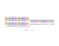 Figure 3-Staple Strands + Plasmid Representation
 -
 Figure 4-Folded Claw
 -
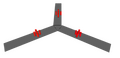 Image:Figure 5-Claw with 5 binding sites
 -
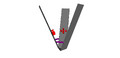 Figure 6-Claw with tethers and 5 binding sites


Modified MS2 capsid
MS2 virus capsid (Figure 7) was provided by Berkeley University. It was modified with single stranded regions in order for to facilitate capsid claw binding (Figure 8), where Figure 9 represents T21 sticky ends, complementary to the A21 sticky ends on the claw.
The blunt capsid is ~22nm in diameter, the single stranded T21 region is ~7nm long, adding a total of ~14nm to the diameter of the capsid.
- Representation of capsid and T21 regions are not to scale.
-
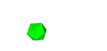 Figure 7-MS2 virus capsid
 -
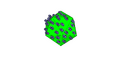 Figure 8-MS2 virus capsid modified with ‘sticky’ region
 -
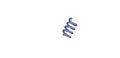 Figure 9-T21 sticky strand


Triangle DO
DO triangle [3] was assembled and modified with A21 sticky ended regions, and trialed as a control experiment in order to illustrate a band shift. (Figure 10)

