BME100 f2014:Group26 L6
| Home People Lab Write-Up 1 | Lab Write-Up 2 | Lab Write-Up 3 Lab Write-Up 4 | Lab Write-Up 5 | Lab Write-Up 6 Course Logistics For Instructors Photos Wiki Editing Help | |||||||
|
OUR COMPANY: ARRAY J
LAB 6 WRITE-UPBayesian StatisticsOverview of the Original Diagnosis System In this experiment, 68 patients were tested for a disease marker to predict their likelihood of developing the disease. These patient samples were divided among 34 teams in the BME 100 class, meaning each team tested two patients' DNA. Each team, consisting of 6 members, received three replicates of each of the patient's DNA and two controls. Within the lab groups, the students worked together to perform image analysis. Errors were attempted to be prevented through multiple avenues, including quantitative results and controls. The replicates of each patient's DNA prevented error, because they allowed for there to be more quantitative data and multiple trials. In addition, there were PCR controls (+/- control samples) that were used in ImageJ for calibration. The controls allowed for a baseline that could be referred to when analyzing patient data. To ensure accuracy, three drop images were analyzed through ImageJ calculations for each patient and for each control. For the final data, of the 68 tests run, 8 of the results were inconclusive, 6 of the results were blank data, and the remaining 54 results led to successful conclusions.
What Bayes Statistics Imply About This Diagnostic Approach For calculation 1, the probability result reflected that the Bayes value was close to 1.00. For the second calculation, the probability was also reflective of the Bayes value being close to 1.00. Based on these values, it can be concluded that the individual PCR replicates are reliable in determining whether or not a person has the disease SNP. Error that may have resulted during the PCR & detection steps could be that the samples were exposed to too much light. If the samples were exposed to more light than the localized beam, such as through improper filtering of light with the light box, it would cause less fluorescence to be emitted from the samples, because it would have been exposed to a frequency other than the LED light source. Another could be incorrect analysis of the samples using ImageJ. The ImageJ analysis could cause error by not analyzing the samples accurately, such as drawing an excessively large or small oval around the sample, or by having too much light surrounding the sample. Another possible source of error could be inadequate photo quality, which would decrease ImageJ's ability to analyze the images to the most accurate degree. For calculations 3 and 4, the Bayes values were very small, indicating that the PCR process is not highly reliable for predicting the development of the disease because the person will most likely not get the disease.
Computer-Aided DesignTinkerCAD TinkerCAD is a 3D computer-aided design (CAD) tool, which operates completely on the Internet. Using a variety of tools, such as highly adjustable shapes and symbols, and grouping and color tools, 3D models can be designed on TinkerCAD and actually produced as objects through 3D printing. To design the OpenPCR machine, various STL (STereoLithography) files representing different parts of the machine were imported from Thingiverse, a website used to share digital design files, to TinkerCAD. The tools on TinkerCAD were then utilized to create a newly designed OpenPCR machine that addressed the limitations that existed with the original design. The components of the fluorimeter were designed entirely on TinkerCAD without the use of imported STL files from Thingiverse.
Our Design
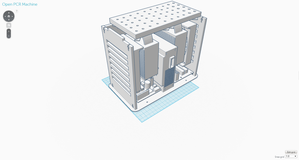
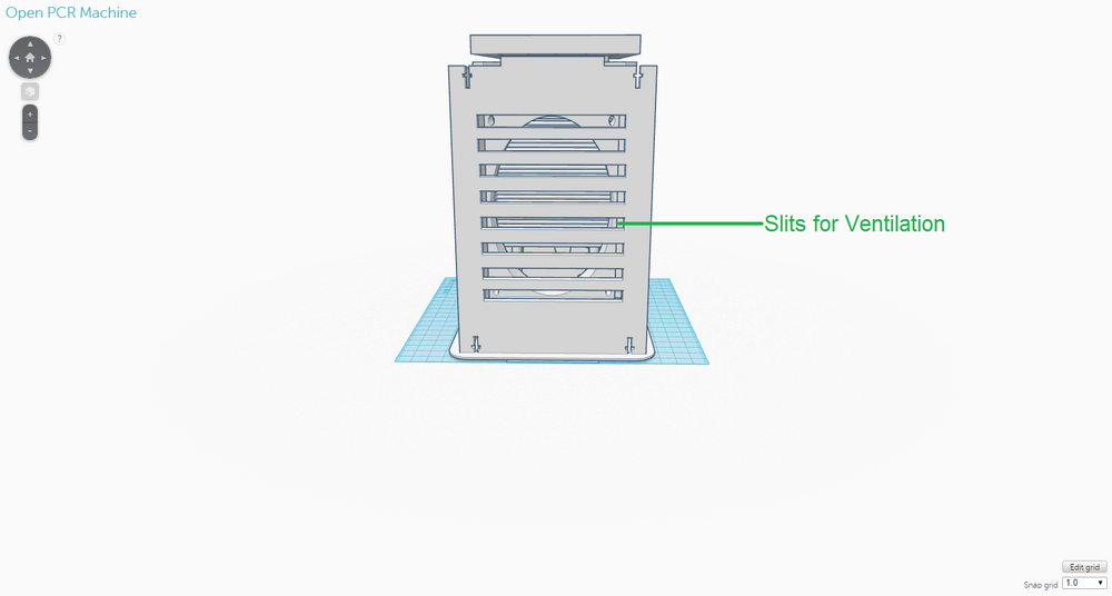
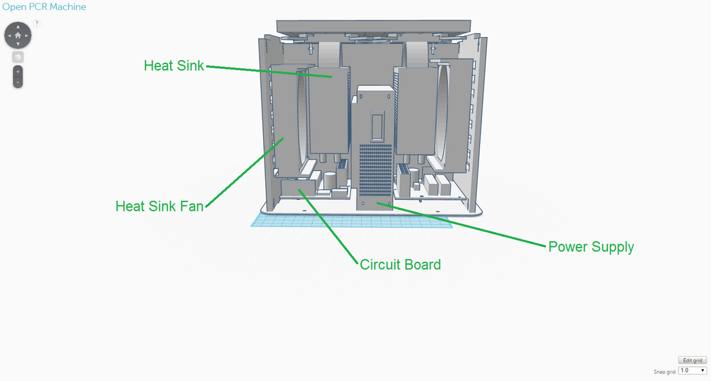
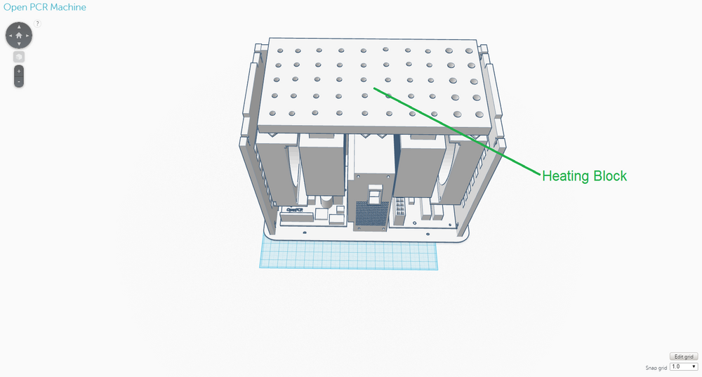
The new design for the OpenPCR machine is not that different from the original one in terms of its components; it expands upon the original one. This design was chosen to address the limitations that existed with the original design, namely the speed of the thermal cycling process and the number of PCR samples that could be handled at one time. The back of the OpenPCR machine retains the ventilation slits the original one had. However, instead of just five slits, there are eight on the new design to allow for the heat sink fans to have improved ventilation. The side of the OpenPCR machine, where all the electronics are located, has one extra of each component that is present in the original design and is much more compact than the original. The top of the OpenPCR machine has an expanded heating block that can handle up to 50 PCR samples at one time. Although these components were not shown in the design, the new OpenPCR machine also has a heating lid and LCD screen to control the machine, just as the original design has.
Feature 1: Consumables KitThe consumables kit will include...
The consumables kit will be packaged in the following manner: Liquid reagents will be packaged in an array of tubes that are all connected to one another and can collectively stand on their own without the use of a tube rack. The tubes will be systemically color-coded and labeled to differentiate the liquid reagents, and the liquid reagents will be provided in more than sufficient amounts to account for possible situations in which the reagents are dispensed erroneously or hastily. The micropipettor will come in one piece and will be ready to use as it is. The micropipettor tips will be packaged in plastic containers identical to the ones in lab. However, the tips will be packaged in such a way that multiple layers of tips will be stacked on top of one another, so that as many tips can be contained in one container and so that plastic usage can be minimized. The tubes to contain the liquid reagents will come exactly as they were used in lab. They can be cut according to the user's needs. Although the packaging of the liquid reagents and the micropipettor tips does not address any particular major weakness of the contents of the consumables kits, they are packaged in this way to minimize the amount of plastic and thus waste that are associated with these components.
Feature 2: Hardware - PCR Machine & FluorimeterOpenPCR Machine Back
OpenPCR Machine Side OpenPCR Machine Top As in the original diagnostic system, the OpenPCR machine will be used after the PCR samples have been prepared with the contents of the consumables kit. The OpenPCR machine will be packaged separated into its individual components and will require that the user assemble the machine. However, instructions will be provided and the components will be designed in such a way that assembly is easy and convenient. One of the major weaknesses of the original OpenPCR machine was that it utilized a thermal cycling process which was considerably slow - The process took a couple of hours and required that the samples were left in the care of someone else. The re-designed OpenPCR machine facilitates this thermal cycling process through specific modifications. For instance, in the back of the OpenPCR machine, there are more slits than the original design to allow for improved ventilation to the heat sink fans, which cool down the system. Cooling down is particularly important in the annealing and final hold stages of PCR. In regards to electronics, the new OpenPCR machine includes two heat sink fans, heat sinks, and circuit boards, as opposed to the original, which only has one of each of the components just mentioned. Again, the additional electronic components were added to improve the system's ability to heat up and cool down in an efficient, timely manner, which are essential to the thermal cycling involved with PCR. The heating block on top of the OpenPCR machine was re-designed to hold a maximum of 50 PCR samples, so that more samples can be tested at one time, if needed, and so that less PCR machines have to be utilized in a setting where PCR samples are being tested in bulk. Fluorimeter
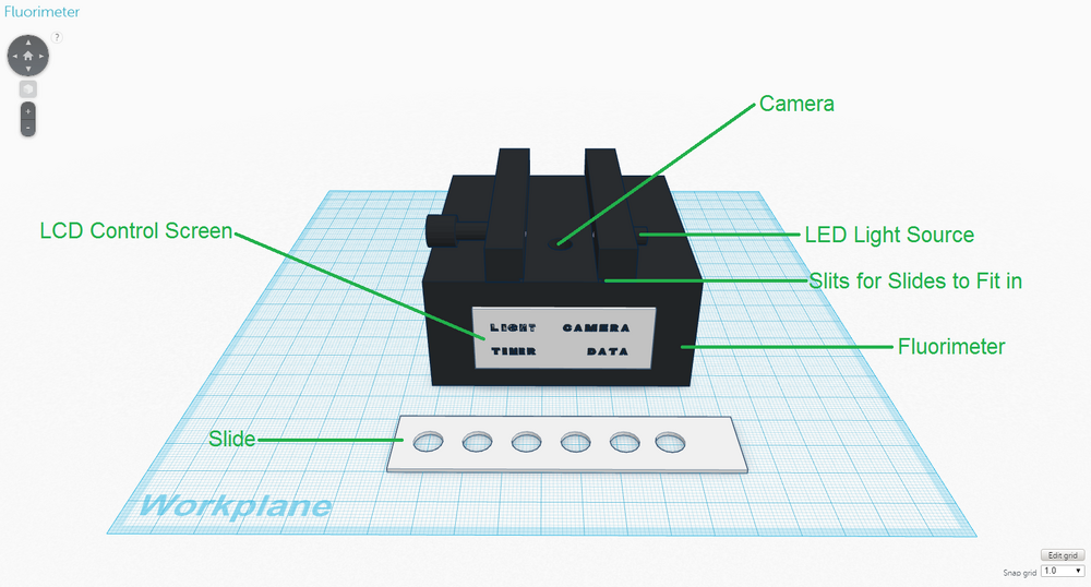
In the new diagnostic system (in the same manner as the original one), the fluorimeter will be used after the samples have undergone PCR in the OpenPCR machine to allow for analysis of the samples and subsequent diagnosis to be performed. The fluorimeter will be packaged as it is shown in the diagram above, and the slides will come with the fluorimeter. One of the major weaknesses associated with the fluorimeter was the phone camera that had to be used to take pictures of the drops for analysis. The phone camera was particularly limiting because it had to be supported by a cradle that could not be moved or adjusted to any extent for accurate measurements. Also, because the pictures had to be taken in complete darkness, it was often difficult making sure that the light box covered the phone camera completely and was sealed before the camera took the picture. Pictures that were not taken in complete darkness often led to inaccurate and unreliable measurements, which are highly consequential considering that the images are used as a basis in diagnosis. To address this weakness, the need for a camera phone and a cradle were completely eliminated by designing the fluorimeter to have a camera built into it, which takes pictures of the drops from below. The highly user-friendly LCD control screen manages all of the functions of the fluorimeter as described below:
Another issue with the original fluorimeter was the way in which the slides were designed. On some occasions, if the drops of the SYBR Green I dye solution and the PCR sample were not placed carefully enough on the slide, the two drops would fail to form a large drop. The sample thus had to be dispensed again, resulting in wasted reagents and time. The newly designed slides have six transparent circles on them, which allow for the fluorimeter's camera to take pictures of the drops from below. The six transparent circles have very slight depressions in them to ensure that drops are properly formed when the SYBR Green I dye solution and PCR samples are dispensed, and to minimize waste. | |||||||


