BE.109:Systems engineering/Advanced bacterial photography: 2 color
Introduction
One approach to understanding what nature has made is to build it yourself. Synthetic chemists may try to synthesize a compound from starting materials to test of their understanding of its chemistry: success offers additional support for the existing model while failure reveals its limits. Similarly efforts to build life from the bottom up can both confirm and advance conclusions drawn from deconstruction experiments that take a cell apart by mutation or through biochemistry.
Biology is particularly well suited to model building since many natural responses appear digital. One example of genetically-encoded digital logic is the heat shock response in bacterial cells. E. coli grow happily at 37°C. Shift them to 42°C and a group of genes, collectively called the heat shock genes, are induced to keep the cell from overheating. The speed with which the induction occurs is remarkable. Full induction is measured in cells after only three minutes at the elevated temperature, allowing gene expression to be modeled as either “on” or “off.” The heat shock promoter can be considered one processing unit that converts environmental information (heat) into transcription units. The heat shock gene is a second processing unit, converting the transcription units generated from the first “black box” into a protein.
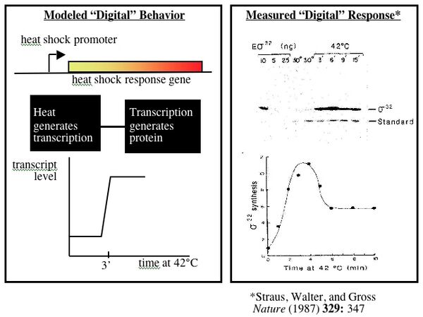
The digital responses of cells to perturbations, combined with lab techniques for moving DNA parts around, allow logic functions and circuits to be constructed in living cells. Consider what would happen if the heat shock gene mentioned above was replaced with a gene for a repressor protein and, through a second manipulation, the repressor-controlled promoter was placed upstream of the heat shock gene. When cells bearing these constructs get shifted to 42°C, the repressor protein would be expressed and would turn off transcription of the heat shock gene. This precisely inverts the logic of the natural response when heat shock genes turn on in response to extra heat.
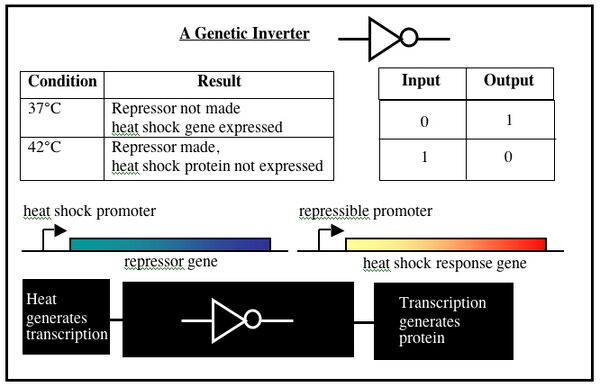
DNA can be programmed to implement other logic functions (AND gates, etc), enabling complex circuits to be built inside a cell. In principle, devices like the genetic inverter could be cleverly combined with other Boolean logic functions to design and synthesize a cell with predictable behavior. In practice, spatial and temporal factors hamper even simple designs. The cell is a messy circuit board without the static physical separation you could find between electronic circuit elements. Proteins are made and roam the cell, invariably interacting with nucleic acids and with other proteins in unpredictable and unspecified ways. A repressor protein might bind a non-consensus DNA elements for example, stressing or changing the behavior of the cell in some unanticipated way.
Circuit composition is also difficult because there is no standard expression level for genetic elements inside a cell. Genes are transcribed and translated at very different rates with wide variations in mRNA and protein stability. So while electrical engineers can find logic gates that will work over a pre-specified range (0-5 volts for example), there are no specifications like these for biological systems. “Polymerases Per Second” (PoPS) is the unit that’s been proposed for measuring gene expression rates (recall your reading in Adventures in Synthetic Biology) but operationally there is currently no simple way to measure PoPS. This creates a problem of “signal matching” as circuits are composed, since the output of one genetic device may be below the threshold of the one it’s designed to drive. At least for now, building complex circuits in cells is still a research effort, relying on trial and error to compose devices successfully. From an engineering perspective, it’s inefficient to try many combinations of genetic parts in realizing a design, akin to building a bridge in order to know if it will fall down. Another problem that both biological engineers and electrical engineers face are meeting the power demands of the system. Biological circuits tend to fail if there aren't enough polymerases, ribosomes, nucleotides and amino acids for system operation and electrical circuits fail if the power supply provides insufficient voltage or current. Finally, all engineers must worry about the impact of noise upon system performance.
In lab today you will invert the logic of the bacterial photography system, then begin your characterization of the system’s output, varying some experimental parameter to assess how that affect a part’s performance. Additionally, in the context of an electrical circuit, you will examine the issue of signal matching in system performance.
Protocol
Part 1: Advanced bacterial photography
The strain you will be using today is similar to the one used for black and white photography but in addition to the output generating device you are familiar with, a second device has been encoded: BBa_M30010. Look at this part at the Registry and try to predict what would happen under light and dark conditions.
| Condition | LacZ (on/off?) | cI (on/off?) | mRFP (on/off?) |
|---|---|---|---|
| Light | |||
| Dark |
BBa_M30000

BBa_M30010

The mRFP protein from basic part BBa_E1010 is detectable in ambient light as red-colored cells. You should use the dual reporter strain (red and black) to take another “biofilm.” You may use the same image as last time or create another one, depending on how happy you were with the results in black and white.
Part 2: Variations in operating conditions
The remainder of this experimental module will be dedicated to measuring the bacterial photography system output under experimental conditions of your choosing. Ultimately, you will document your findings at the Registry of Standard Biological Parts, allowing others to be informed by your experience with this system.
Think about what might be an interesting variation on the standard protocol and then plan a way to vary it. Experimental changes that affect growth might be good ones to try since cells will express unessential genes less well when they are stressed (by starvation, suboptimal temperatures, unusual pH etc). Other interesting experimental variations might relate to the light detection set-up itself, changing the intensity or spectrum of the light. Not every variation is possible but the teaching faculty will do their best to help you refine and then realize your plan. Before you leave lab today you should be growing 5 ml of the bacterial photography strain under two conditions. Next time you will compare the LacZ production (protein and RNA) in these cultures.
Part 3: Biological versus electrical devices
In this section, we'll explore the issue of signal matching in the context of an electrical circuit. As you work through this exercise, consider how the lessons learned from experimenting with circuit would map to the engineering of biological systems. Along the way, you'll be asked questions about the circuit, answer them in your lab notebook.
Safety information
In this exercise, you'll be working with circuits connected to power supplies. Practice good habits by never touching the circuit without first turning the power supply off (and verifying that it is off!).
System description
The focus of Module 3 is on a bacterial photography system. As you know, this system is constructed from two devices.
- Sensor: a device which, in response to dark, produced a PoPS output signal. (See the Adventures in synthetic biology comic for a refresher about PoPS.)
- Actuator: a device which takes an input signal in PoPS and produces beta-galactosidase activity.
We can construct an analogous system from electrical components. A photodiode is a light sensor and an LED is responds to an input by emitting colored light. Hence, it is an actuator. We can thus use these two devices to build a circuit that will operate similarly to our bacterial photography system: it will sense light and produce a corresponding color.
System design
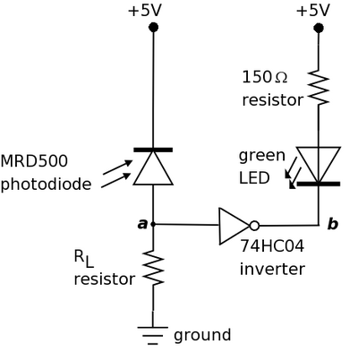
This system is fairly simple one since it only consists of a few components. In contrast to the bacterial photography system in which the signal is encoded in PoPS, here signals are propagated as either voltage or current. As you can see in the schematic, it contains the following parts.
- Photodiode: light sensor whose resistance decreases in the presence of light such that more current flows through it.
- LED: device which responds to a voltage drop across its terminals by emitting colored light.
- Resistor: component which resists current flow by producing a voltage drop across it.
- Inverter: a logic device which inverts its input signal.
For more information on these parts, consult the parts datasheets linked below.
The purpose of the photodiode is to serve as a light sensor (like Cph8 and the phycobilins) and the LED as a readout (like lacZ). The 150Ω resistor is there to ensure that the voltage drop across the LED isn't too high (which can cause the LED to breakdown). The inverter provides a convenient way of connecting the photodiode to the LED. The other resistor RL is there to ensure that the signal between the photodiode and inverter are matched. When light shines on the photodiode, its resistance is decreased and current flows through it. Thus, point a in the circuit diagram is at high voltage (near +5V) and the input signal to the inverter is high. The low output signal (point b) from the inverter creates a voltage drop across the LED causing it to turn on and emit light. In the absence of light, the photodiode has high resistance such that little current flows. Point a in the diagram is at low voltage (near 0V) and the inverter produces high output at point b. The resulting lack of voltage drop across the LED means that the LED is turned off. Much of this exercise will focus on RL and ensuring that the signal between the photodiode and inverter are matched for proper circuit operation.
System operation
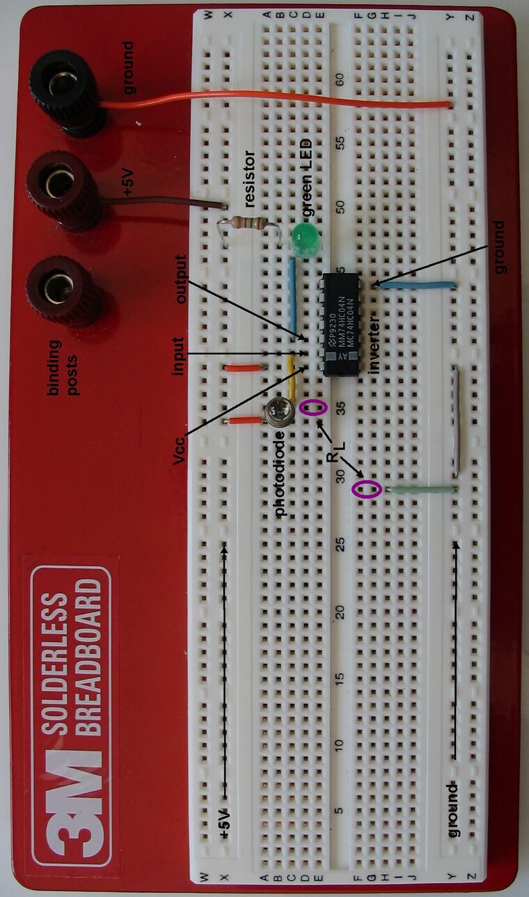
Most of this circuit has been implemented for you. To help you understand the system, there is a picture of your wired up circuit with the different components of interest labelled. Comparison of the photo with the circuit diagram above should show that the circuit is wired up as shown in the diagram.
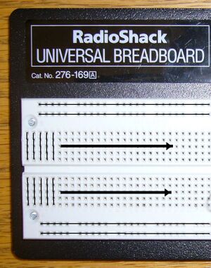
The circuit has been constructed using a breadboard which is a convenient way to construct electrical circuits. The breadboard holes are connected as shown in the photo. Take note of these connections because they'll affect how you will connect up resistors in this exercise.
Examining the extremes of system behavior
Now let's familiarize ourselves with the system. To begin, you'll examine the two extreme cases for the value of the RL resistor: 0Ω and ∞Ω. Connect the binding posts on the breadboard to the power supply making sure you don't mix up the +5V and the ground. Now turn on the power supply and verify that it is set to +5V. (The display should read 5.00 and the CV light should be on indicating that the power supply is producing constant voltage.)
- What happened? Is the LED light on or off?
Notice that in fact your circuit differs slightly from the one in the photo. There is no RL resistor connecting the photodiode (point a) and ground. Thus, it is as if your circuit has infinite resistance between point a and ground (absolutely no current can flow).
- Explain why you observe the behavior you do given that there is infinite resistance between the photodiode and ground.
Examine the other extreme case. Connect a wire between ground and the photodiode. Sample connection points are indicated in the circuit photo with purple circles. Wires tend to have very little resistance so this is almost putting a resistor of 0Ω between the two points.
- What happened? Is the LED light on or off? Explain why you observe the behavior you do given that there is almost no resistance between the photodiode and ground.
This is a general technique that engineers to use to understand a system: they look at the simple, extreme cases and try to reason out the behavior of the circuit.
Construct a functioning circuit

Now that you've explored the two extremes, let's try to actually build a functioning circuit. If you think back to physics, Ohm's law define the relationship between voltage, current and resistance.
[math]\displaystyle{ V=IR }[/math]
We can use this formula to calculate loose bounds on RL that will yield a working circuit.
[math]\displaystyle{ \frac{V_{IH}}{Light Current} \lt R_L \lt \frac{V_{IL}}{Dark Current} }[/math]
- VIL: Highest voltage at point a that is a low input signal for the inverter.
- VIH: Lowest voltage at point a that is a high input signal for the inverter.
- Light Current: Current that flows through the photodiode when light is shone on it.
- Dark Current: Current that flows through the photodiode when it is in the dark.
Conveniently, inverters and photodiodes have been characterized so well that their performance is very well-documented. (Contrast this to parts in the Registry of Standard Biological Parts in which very few parts have any characterization data at all. We have a long way to go!) You should be able to obtain values for VIL and VIH from the inverter datasheet linked below and values for the light and dark current from the photodiode datasheet. These datasheets have far more detail than the sample datasheet for BBa_F2620 shown.
- Determine values (with units!) for the four variables from the datasheet and explain from where on the datasheet you retrieved them. Then calculate the bounds on RL to help narrow your search for a resistor or resistors that will lead to a working circuit.
These bounds will not be exact because the performance of real components deviates some from the model predicted by the equation. Nonetheless, this calculation should give you a place to start for finding an RL that gives a working circuit.
Now, via trial and error, try to find a resistor or series of resistors (resistors connected end to end) for RL that lead to proper circuit operation: in the light, the LED is on and in the dark, the LED is off. Make sure that one resistor end is connected to the photodiode and the other to ground (as shown by the purple circles in the circuit photo). You will need to verify that you are wiring up the resistors properly given the layout of connections on the breadboard! Use the resistor color code table linked below to check that you are using resistors of the resistance you want.
- What resistance value for RL gives a working circuit?
Notice how much easier it is to assemble electrical circuits as compared to biological circuits. It takes seconds to swap in a new resistor into your circuit but a few days to assemble two BioBricks together!
Sensitivity of system function to RL
Next, let's determine how sensitive system performance is to the value of RL.
- How large can RL be and yet have the circuit still work? How small?
You don't need to determine the exact range for RL but getting approximate, experimentally-determined limits gives you an idea of how robust the circuit is to RL. This is analogous to determining how sensitive an engineered biological system is to RBS strength or protein-DNA binding affinity. But again, it is much easier to do this experiment with an electrical circuit.
Comparing resolutions
In fact, the bacterial system does have one important advantage over this electrical circuit. It is much easier to generate lots of copies of a bacteria than lots of copies of your electrical circuit.
- Compare the resolution of a bacterial photograph with that of a photodiode array assembled from many MRD500 photodiodes. What about a typical digital camera on the market these days? Which one has the best resolution? The worst?
Optional
Notice that in fact this electrical circuit behaves opposite the bacterial photography system. The LED readout is on when light shines on the photodiode. In contrast, in the bacterial system, the lacZ readout only occurs for cells in the dark.
- To impress your TA and lab instructor, propose a redesign of this circuit that will yield the same behavior as the bacterial photography system.
Parts datasheets & other useful information
Acknowledgements
Many thanks to Tom Knight and Barry Canton for invaluable contributions to this exercise.
Part 4: Science and society
The remainder of the lab period has been set aside for you to think further about Synthetic Biology as an emerging technology and to discuss your ideas with the group. Begin by reading The engineer's approach to biology by Holger Breithaupt and Foundations of engineering biology by Drew Endy, and then consider what incomplete knowledge of biology means for efforts to engineer biology. How do engineers traditionally deal with complexity? Would similar methods work in biological engineering? What about the pressure that evolution exerts on living systems, particularly as they are strained and challenged? Do current risk estimates for naturally occurring biological organisms apply as well to engineered life? By the end of today’s lab you should have
- contributed to the conversation
- clarified your thinking about the challenges and risks associated with synthetic biology
- gathered some techniques for writing a persuasive argument
DONE!
For next time
Continue your writing assignment, focusing on your look to the future. Describe some of the best and/or worst applications of synthetic biology that may enrich/endanger society. Specifically you should make a chart. On the right side you should list 5 suitable, interesting, useful applications for synthetic biology. What would you love to see genetically programmable cells doing? Be clear about the benefit(s) these cells could offer. You do not need to figure out how you would make the cells do the things you propose (unless you want to). On the left of your chart, you should list at least one risks associated with each of the applications you describe. For example light-responsive cells capable of taking a picture may morph into light-responsive toxin-producers that could decimate Gotham every sunny day. Finally, make a wish list of at least 10 things that will be needed to achieve the applications you envision. These things can include improvements to currently available technologies, additional financial resources, improved understanding of biology, new trade/criminal/patent laws, changes to the social structure around research. Consider anything but be specific with your wish list (e.g. say “de novo DNA synthesis costs must fall below $0.001/base” rather than “more DNA synthesis”)
Next you should specify a part integral to your own system idea. You should retrieve sequence for at least one of the new parts you will include in your system and add the part to the registry, including "biobrick" ends and useful annotation as you do so. Print out the page with your new part number to hand in next time. If there are no new parts to your proposed system, or if the sequences you need to build with are not currently known, then use NCBI as a resource and specify something that is not currently in the registry but that might be useful to future genetic programmers.
