20.109(F10): Mod 2 Day 3 Tools for system engineering: Difference between revisions
| Line 64: | Line 64: | ||
===Part 4: Modeling biological versus electrical devices=== | ===Part 4: Modeling biological versus electrical devices=== | ||
In this section, we'll explore the issue of signal strength in the context of an electrical circuit. As you work through this exercise, consider how the lessons learned from experimenting with an electronic circuit would map to the engineering of biological systems. | In this section, we'll explore the issue of signal strength in the context of an electrical circuit. As you work through this exercise, consider how the lessons learned from experimenting with an electronic circuit would map to the engineering of biological systems. You will be given a kit to construct this circuit. | ||
[[Image:PhotoElectronics.jpg|thumb|left|250px|'''starting kit''']] | |||
====Acknowledgements==== | ====Acknowledgements==== | ||
Many thanks to [[Tom Knight]], [[Reshma Shetty]] and [[Barry Canton]] who motivated and designed an early version of this exercise. And a special shout out to Steve Wasserman for his guidance in redeveloping, troubleshooting and building this circuit to more directly reflect the experiment we're performing. | Many thanks to [[Tom Knight]], [[Reshma Shetty]] and [[Barry Canton]] who motivated and designed an early version of this exercise. And a special shout out to Steve Wasserman for his guidance in redeveloping, troubleshooting and building this circuit to more directly reflect the experiment we're performing. | ||
| Line 72: | Line 73: | ||
When you connect the battery to the breadboard, make sure you do so in the correct orientation for the circuit (red to red, black to ground) or the OpAmp will break...really. | When you connect the battery to the breadboard, make sure you do so in the correct orientation for the circuit (red to red, black to ground) or the OpAmp will break...really. | ||
====System design==== | ====System design==== | ||
[[Image:RevisedCircuitDiagram BactPhoto.png|thumb| | [[Image:RevisedCircuitDiagram BactPhoto.png|thumb|center|400px|'''A diagram of the electrical circuit that is analogous to the bacterial photography system.''' Circuit designed by Steve Wasserman]] | ||
<br style="clear:both" /> | |||
This system is fairly simple one since it only consists of a few components. In contrast to the bacterial photography system in which the signal is propagated through protein activities, here signals are propagated as either voltage or current. As you can see in the schematic, the circuit contains the following parts. | This system is fairly simple one since it only consists of a few components. In contrast to the bacterial photography system in which the signal is propagated through protein activities, here signals are propagated as either voltage or current. As you can see in the schematic, the circuit contains the following parts. | ||
#[[Media:Photodiode SpecSheet.pdf| Photodiode]]: #LT959X-91-0125: a light sensor ''(mimics Cph8 and the phycobilins)''. When light shines on the photodiode, its resistance is decreased and current flows through it. | #[[Media:Photodiode SpecSheet.pdf| Photodiode]]: #LT959X-91-0125: a light sensor ''(mimics Cph8 and the phycobilins)''. When light shines on the photodiode, its resistance is decreased and current flows through it. | ||
| Line 78: | Line 80: | ||
#[http://www.breakup.de/resources/resistor.html Resistor]: components which resists current flow by producing a voltage drop across it. The gain in this system is proportional to the resistance, and by varying the resistance into the OpAmp, the sensitivity of the circuit to light can be tuned. | #[http://www.breakup.de/resources/resistor.html Resistor]: components which resists current flow by producing a voltage drop across it. The gain in this system is proportional to the resistance, and by varying the resistance into the OpAmp, the sensitivity of the circuit to light can be tuned. | ||
#[http://www.allelectronics.com/make-a-store/item/LED-2/GREEN-5MM-T1-3/4-LED//1.html LED]: a device with a detectable output ''(mimics LacZ)''. A voltage drop across its terminals turns the green-colored light on. The 820Ω resistor is added to the circuit before the LED to ensure that the voltage drop across the LED isn't too high (which can cause the LED to breakdown).<br> | #[http://www.allelectronics.com/make-a-store/item/LED-2/GREEN-5MM-T1-3/4-LED//1.html LED]: a device with a detectable output ''(mimics LacZ)''. A voltage drop across its terminals turns the green-colored light on. The 820Ω resistor is added to the circuit before the LED to ensure that the voltage drop across the LED isn't too high (which can cause the LED to breakdown).<br> | ||
===Let's start building=== | ===Let's start building=== | ||
Revision as of 20:10, 4 October 2010
Tools for system engineering
Introduction

The region of the Cph8 protein to focus on for this purpose has been defined through traditional scientific studies of EnvZ, for example the work from Tom Silhavy's lab( PMID: 9721293 and pdf here). We've also been guided by the expertise of MIT's Mike Laub, whose lab studies the specificity and rewiring of two component regulatory systems. From these sources, a span of 5 contiguous amino acids can be identified as relevant for shifting the balance of EnvZ to greater kinasing or greater phosphatasing activity. These five residues in EnvZ are Alanine at amino acid 239 ("A239") through Histidine at amino acid 243 ("H243"), where mutations in the flanking residues (A239 and H243) have been shown to enhance the phosphatase activity of EnvZ and mutations in the internal residues (G240 V241 S242) enhance the kinase activity of EnvZ. The amino acid changes that modify the enzymatic activities are indicated on the figure below. Two important notes about these mutations though: First, the balance of kinase to phosphatase activities have been affected by the changes, but the mutations do not shift the reactions to fully "on" or fully "off." Second, the fusion protein of Cph1 to EnvZ, called Cph8, changes the numbering of the residues, as shown in the figure below. It's hoped, however, that the local environment of the region is similar to the natural EnvZ protein. 
To complement the genetic approach for solving biological engineering puzzles, we'll also consider three other approaches in synthetic biology. The first is a Registry of Standard Biological Parts, essentially a community resource that has some ready-made and useful genetic elements that can be assembled into synthetic biological devices systems. The second approach is to use the Tinkercell computer model to simulate the behavior of the bacterial photography system, with the goal of performing "in silico" experiments that would take days or weeks to do at the bench. And finally, in the third approach, we'll recapitulate the genetic network of the biological system using electronic components, making explicit some of the benefits and limitations of such an approach and the often-cited analogy between building with biology and building with computer programs or electronic components.
Protocols
Before you leave today, you should examine the bacterial photograph you set up last time and document your work and your ideas about the experiment.
Part 1: Library Screen
The details for how the libraries were constructed and what kinds of changes are reasonable to expect will be considered in the next lab session. For today, you will transform a pool of DNA with degeneracies in the positions that affect the kinasing activity of EnvZ. The recipient bacterial strain is identical to the bacterial photography system except that it does not harbor a plasmid encoding the light-sensing fusion protein Cph8. It does encode the OmpR-regulated LacZ gene as well as the phycobilins from a plasmid.
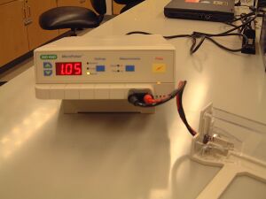
- When you are ready to electroporate the library, retrieve an aliquot of cells from the teaching faculty, a sterile cuvette, and an aliquot of rich, pre-warmed "SOC" media.
- Put the cuvette on ice.
- Pipet 2 ul of the library DNA that is being held in an icebucket on the teacher's bench into your aliquot of cells.
- Let the cells and the DNA incubate on ice one minute.
- Transfer 50 ul of the cells (or more if the tube has more volume) to the chilled cuvette and recover it with the blue lid.
- Put on your safety goggles.
- Tap the cuvette on the bench so the cells rest in the bottom of the cuvette.
- With the cuvette's "nub" facing away from you, slide the cuvette into the electroporation chamber. Push the slide into the chamber until the cuvette is between the metal contacts. The lid on the cuvette will seem to block the path but in fact, it doesn't block the slider if you've lined thing up.
- Make sure the electroporator is set to "Ec2"
- Hold the pulse button until you hear a beep. Listen carefully since the beep is not loud.
- Quickly remove the cuvette from the holder and immediately add the 0.5 ml volume of "SOC" media to the cells. Delaying this addition by even 1 minute has been seen to decrease transformation by 3 fold.
- Transfer the cells and the media back to an eppendorf tube and place the tubes on the nutator in the 37° incubator for 1 hour. During this incubation you can work on Parts 2, 3 and 4 of today's protocols.
- Spread 50 ul of the electroporation mix onto a Tetrazolium+Cam34+Amp200 petri dishes. Plate 300 ul of the electroporation mix on another Tetrazolium+Cam34+Amp200 petri dish. One of these two dilutions should have single, well-isolated colonies to examine next time. Incubate the plates at 37° in the dark until next time.
Part 2: Registry of Standard Biological Parts
What would it take to make DNA serve as a low-level programming language so that a genome is simply a particular program?
- DNA, like software, has an alphabet but with only four letters in the genetic code.
- Since there are proof-reading mechanisms in the "hardware," i.e. in the cell, syntax errors may be less likely to arise than in Python or Perl or C++.
- The code for cellular programs is messy but, honestly, so are computer programs. Subroutines are often dependent on one another (the cell cycle and DNA replication for example) and parts of the program get reused in useful, but complicated and unpredictable ways (seen as cross-talk in signaling pathways for example).
- Genetic code and computer code are both susceptible to viruses that highjack normally benign functions.
The analogy of the DNA as computer code is not perfect. We have to set aside the presumption of an intelligent agent responsible for writing the initial program as well as accept that natural events will change the code over time (evolution leading to genetic variation--the very thing we're trying to harness in the first part of today's lab). And no good tools exist for systematically debugging the genetic code.
What would make genetic code easier to write? One idea is to make it a more “object oriented” language, defining units of known function that could be combined in standard and predictable ways. One effort to facilitate genetic programming can be found at The Registry for Standard Biological Parts. The Registry is a catalog of parts that describe basic biological functions. For example BBa_B0010 is the part number for a transcriptional terminator. The Registry of Standard Biological Parts makes its parts freely available to interested researchers and engineers, and allows registered users to add and annotate parts.
To familiarize yourself with the Registry, you'll design a protein-generating device for E. coli. This device will consist of at least 3 parts from the Registry: an ORF, a promoter and a ribosome binding site (RBS).
Finding a protein coding part
Try using the "catalog of parts and devices" (the leftmost icon here) to search for a part you'd like to use. Start your search in the "protein coding sequences" and then identify one of interest to you and your lab partner.
- What part number have you chosen?
- Follow the link to the data page associated with part. Is anything specified about its use or performance?
Finding a promoter part
Try finding this part with the "search parts" function (under the Registry tools list on the right-hand side of the page that's here.)
- Did you search by text, by part number, or by subpart? What worked and how well?
- What part number have you chosen?
- What can you learn about the regulation of transcription from this part's number? part's name? part's information at the Registry?
- Follow the link to the data page associated with this part. Is anything specified about its use or performance?
Finding an RBS
To find an RBS you should restrict your search to a set of the Registry's well-characterized ones from Chris Anderson's lab or the community collection, several of which are from Ron Weiss' lab.
- What part number did you choose?
- Can you anticipate the strength of this RBS in your three part construct? Why or why not?
NOW: In plain English, what behavior do you expect for your three part construct? You should include this answer in your lab notebook and if you choose to do the optional "for next time" assignment, you can use this example as a point of departure for your discussion.
Assembly of this construct
Part of the usefulness of the Registry is that the parts conform (mostly) to a standardized assembly scheme. This scheme enables the same restriction enzymes to be used to physically piece together parts in series. The scheme does not ensure functional assemblies, however. If you have time before your cells are ready today or before the electronics exercise, then you can familiarize yourself with this "BioBrick™ assembly scheme."
Part 3: CAD tool for synthetic biology
Revisit the visual model for the bacterial photography system that you assembled using Tinkercell last time. Today you will run a deterministic simulation according to slides 16-23 in the linked tutorials found here and here.
Part 4: Modeling biological versus electrical devices
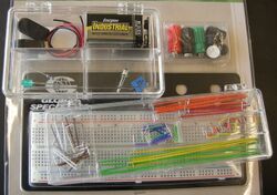
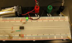
In this section, we'll explore the issue of signal strength in the context of an electrical circuit. As you work through this exercise, consider how the lessons learned from experimenting with an electronic circuit would map to the engineering of biological systems. You will be given a kit to construct this circuit.
Acknowledgements
Many thanks to Tom Knight, Reshma Shetty and Barry Canton who motivated and designed an early version of this exercise. And a special shout out to Steve Wasserman for his guidance in redeveloping, troubleshooting and building this circuit to more directly reflect the experiment we're performing.
Safety information
In this exercise, you'll be working with circuits connected to a battery. Practice good habits by never touching the circuit without first unplugging it.
- also please note:
- also please note:
When you connect the battery to the breadboard, make sure you do so in the correct orientation for the circuit (red to red, black to ground) or the OpAmp will break...really.
System design
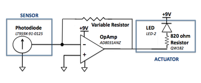
This system is fairly simple one since it only consists of a few components. In contrast to the bacterial photography system in which the signal is propagated through protein activities, here signals are propagated as either voltage or current. As you can see in the schematic, the circuit contains the following parts.
- Photodiode: #LT959X-91-0125: a light sensor (mimics Cph8 and the phycobilins). When light shines on the photodiode, its resistance is decreased and current flows through it.
- OpAmp: #AD8031ANZ: a logic device that detects a difference in + and - current inputs and amplifies it.
- Resistor: components which resists current flow by producing a voltage drop across it. The gain in this system is proportional to the resistance, and by varying the resistance into the OpAmp, the sensitivity of the circuit to light can be tuned.
- LED: a device with a detectable output (mimics LacZ). A voltage drop across its terminals turns the green-colored light on. The 820Ω resistor is added to the circuit before the LED to ensure that the voltage drop across the LED isn't too high (which can cause the LED to breakdown).
Let's start building
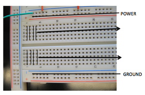
- Power the board by running a wire from the +V source (the red plug) to the red + connection at the "top" of the breadboard.
- Run the blue - connection at the "bottom" of the breadboard to the black, ground plug.
Examining the extremes of system behavior
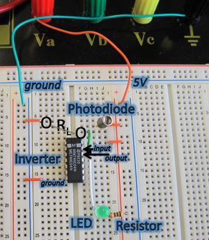
A general technique that engineers use to understand a system is they look at the simple, extreme cases and try to reason out the behavior of the circuit. We'll try this to familiarize ourselves with the system. Most of this circuit has been implemented for you. Comparison of the photo (below) with the circuit diagram (above) should show that the circuit is wired up as shown in the diagram with the exception of the RL resistor. To begin, you'll examine the two extreme cases for the value of the RL resistor: 0Ω and ∞Ω.
Case 1: RL resistor = ∞Ω
- What happened? Is the LED light on or off?
- Explain why you observe the behavior you do given that there is infinite resistance between the photodiode and ground.
Case 2: RL resistor = 0Ω
Now examine the other extreme case. Connect a wire between ground and the photodiode. Sample connection points are indicated in the circuit photo with circles. Wires tend to have very little resistance so this setup is almost like putting a resistor of 0Ω between the two points.
- What happened? Is the LED light on or off?
- Explain why you observe the behavior you do given that there is almost no resistance between the photodiode and ground.
Constructing a functional circuit
Now that you've explored the two extremes, let's try to actually build a functioning circuit. If you think back to physics, Ohm's law defines the relationship between voltage, current and resistance.
[math]\displaystyle{ V=IR }[/math]
We can use this formula to calculate loose bounds on RL that will yield a working circuit.
[math]\displaystyle{ \frac{V_{IH}}{Light Current} \lt R_L \lt \frac{V_{IL}}{Dark Current} }[/math]
- VIL: Highest voltage at point a that is a low input signal for the inverter.
- VIH: Lowest voltage at point a that is a high input signal for the inverter.
- Light Current: Current that flows through the photodiode when light is shone on it.
- Dark Current: Current that flows through the photodiode when it is in the dark.
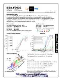
You should be able to obtain values for VIL and VIH from the inverter datasheet (also linked above) and values for the light and dark current from the photodiode datasheet.
With this calculation, you should see how helpful it is that inverters and photodiodes have been extensively characterized and that their performance is well-documented. Contrast this to parts in the Registry of Standard Biological Parts in which very few parts have any characterization data at all. We have a long way to go!
Case 1: calculation
Determine values (with units!) for the four variables from the datasheet and explain from where on the datasheet you retrieved them. Then calculate the bounds on RL to help narrow your search for a resistor or resistors that will lead to a working circuit. These bounds will not be exact because the performance of real components deviates some from the model predicted by the equation. Nonetheless, this calculation should give you a place to start for finding an RL that gives a working circuit.
Case 2: trial and error
Try to find a resistor or series of resistors (resistors connected end to end) for RL that lead to proper circuit operation: in the light, the LED is on and in the dark, the LED is off. (Notice this is the reverse of the signaling in the bacterial photography system, as we'll consider later). Make sure that one resistor end is connected to the photodiode and the other to ground (as shown by the circles in the circuit photo). You will need to verify that you are wiring up the resistors properly given the layout of connections on the breadboard! Use the resistor color code table to check that you are using resistors of the resistance you want.
- What resistance value for RL gives a working circuit?
- How large can RL be and yet have the circuit still work? How small?
You don't need to determine the exact range for RL but getting approximate, experimentally-determined limits gives you an idea of how robust the circuit is to RL.
DONE!
For Next Time
1. Draft your Materials and Methods section for your Mod 2 research article. You can describe the strains and plasmids you've used, the mechanics of taking a bacterial photograph, the b-gal assay and the library screen as far as through the electroporation. The due date for this assignment will vary depending on if you are presenting a Journal Club article next time as well.
- If you ARE NOT giving a journal club talk next time, then this draft is due next time
- If you ARE giving a journal club talk next time, then this draft is due before lab, one week from today.
2. If you are giving a journal club talk, the slides for your presentation should be uploaded to the Stellar website that is associated with our class. The presentation order will be determined by the order that your finished slides are uploaded.
3. (OPTIONAL): Comparisons of biological engineering and electrical engineering. Today's lab work may have made clear how much easier it is to assemble electrical circuits and run computer simulations of them than it is to assemble and test biological circuits. For example, it takes seconds to swap in a new resistor into your circuit or modulate an experimental parameter in the CAD tool, but it takes a few days to assemble DNA fragments (BioBricks or not). What other comparisons can you make that emphasize the
- sensitivity of system performance
- resolution
- fabrication
- repair
- ???
of the two types of circuits.
Reagents
- for electroporation
- Strain NB188 (genotype: MC4100 ara+ Φ(OmpC-lacZ) 10-25 ΔenvZ::KanR +pPL-PCBamp)
- pCph8 library: see Day 5
- SOC media
- 0.5% Yeast Extract
- 2% Tryptone
- 10 mM NaCl
- 2.5 mM KCl
- 10 mM MgCl2
- 10 mM MgSO4
- 20 mM Glucose
- LB + Amp + Cam plates
- 1% Tryptone
- 0.5% Yeast Extract
- 1% NaCl
- 2% Agar
- 100 ug/ul ampicillin
- 34 ug/ul chloramphenicol
