Dielectrophoresis - Melissa Deschamps
Introduction
Dielectrophoresis (DEP) is the movement of a particle due to the application of a non-uniform electric field. Dielectrophoresis was first studied in depth during the 1950’s by Herbert A. Pohl where the focus was first removing suspended particles from polymer solutions [1]. The process is related to the electrophoresis phenomenon where an electrostatic field causes motion of charged particles. Dielectrophoresis is the movement of neutral particles due to a dielectrophoretic force which on average has a smaller effect than electrophoresis [2]. The phenomena can be ascribed to the interaction of the non-uniform electric field with its dipoles, either permanent or induced, and expressed through the dielectric constant. This process is being widely investigated for cells isolation application, cell-based drug discovery procedures development, electronic sensors and nanoparticles assembly [3].
Background and Theory
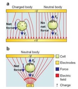
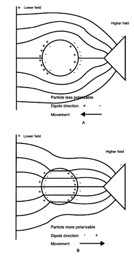
A dielectric particle is placed in an electric field where it becomes electrically polarized as a result of the partial charge separation which leads to an induced dipole moment. Fig 1b is a representation of this phenomena. The dipole movement is the consequence of equal and opposite charges [4]. The magnitude of the dipole depends on the polarizability of the particle and the type of medium. If the polarizability of a particle is higher than the medium, the particle will go towards regions of higher electric field. If the medium has higher polarizability, the particle will be driven towards the low field-strength region [5]. These are called positive DEP and negative DEP, respectively (See Fig 2). Current research has developed to the stage where enough information is known on the dielectric properties so that new technologies can be developed and applied in fields such as biotechnology.
Dielectrophoretic Force
A particle in an electric field experience the lateral force described in equation one.
[math]\displaystyle{ \bar{F}_\mathrm{elec} =q\bar{E}+(\bar{m}\nabla\bar{E}+\frac{1}{6}\nabla(\overrightarrow{Q}:\nabla\bar{E})+... (1) }[/math]
Where [6]:
[math]\displaystyle{ \nabla }[/math] is the del operator
[math]\displaystyle{ q\bar{E} }[/math] is interaction between the net charge of particle [math]\displaystyle{ (q) }[/math] to the electric field [math]\displaystyle{ (\bar{E}) }[/math]
[math]\displaystyle{ \bar{m} }[/math] dipole force component
[math]\displaystyle{ \overrightarrow{Q} }[/math] is the Quadrupole Tensor
The time-averaged DEP force due to an imposed electrical field can be approximated in terms of dipole effects for a sphere using equation one [6].
- [math]\displaystyle{ \langle F_\mathrm{DEP} \rangle = 2\pi r^3\varepsilon_m \textrm{Re}\left\{\frac{\varepsilon^*_p - \varepsilon^*_m}{\varepsilon^*_p + 2\varepsilon^*_m}\right\}\nabla \left|\vec{E}_{rms}\right|^2 (2) }[/math]
Where
[math]\displaystyle{ \nabla \left|\vec{E}_{rms}\right|^2 }[/math] is the gradient of the square of the electric field quantifying the non-uniformity of the electric field
[math]\displaystyle{ 2\pi r^3\varepsilon_m }[/math] is the surface area of square
[math]\displaystyle{ {Re} }[/math] Takes real component of the Clausius-Mossotti Factor
[math]\displaystyle{ \varepsilon }[/math] permitivity
The Clausius-Mossotti Factor, equation 3, is the effective polarizability of the particle and its medium [5]
[math]\displaystyle{ \frac{\varepsilon^*_p - \varepsilon^*_m}{\varepsilon^*_p + 2\varepsilon^*_m} (3) }[/math]
Where
[math]\displaystyle{ \varepsilon^*_p, \varepsilon^*_m }[/math] is the complex dielectric characteristics of the particle and the medium [math]\displaystyle{ \varepsilon^*=\varepsilon=-j\omega\sigma }[/math] [5]
[math]\displaystyle{ \sigma }[/math] conductivity
[math]\displaystyle{ \omega }[/math] angular frequency
The above equation has a few simplifications to get the final form. The particles are considered to be homogeneous dielectrics and show no conductive losses. A simple dipole moment in an infinite medium is also assumed. The equation also does not take in account the presence of a boundary layer. However this deviation portrays key features of the process. The DEP force is zero in a uniform electric field. The DEP force depends on the particle's volume; the greater the volume, the greater the force. Finally, the direction of the particle, towards or away from the electrode, is dependent on the medium and the particle’s permittivity [3]. The DEP force depends more on the conductive properties at low frequencies and more on the permittivity values at high frequencies.
Applications Overview
The first patent using DEP was granted in 1924 and was for the separating minerals (4). Comminution is an energy intensive process used in the mining process. Dielectrophoresis was reviewed as a better technique for the removal of course grains in order to lessen the amount of material going on to finer grinding processes [6]. Due to the properties of dielectrophoresis there is much interest in recent years to develop new technologies for applications in the study of micro-scale systems. The popularity of dielectrophoresis in micro-scale research is due to the fact that the required voltage requirements decrease with smaller length scales.
[math]\displaystyle{ F_{DEP}\approx V^2/L^3 }[/math]
When a system goes from a characteristic electric field length (L) of 1 cm to 100 μm, the voltage can be reduced by 1000 V while keeping the force constant. Therefore, one can achieve a higher force by decreasing the length of the system [6]. Current research is focused on how to manipulate and sort particles and analytes in microfluidic and micrototal analysis systems. DEP depends on many characteristics such as size and composition which makes the process tunable to specific mixtures. In addition, the process does not require expensive fabrication methods and the apparatuses can be produced with conventional electronics that eliminate the need for expensive and complex mechanical pumps [7]. DEP is mainly used as a characterization tool to collect rate, crossover and particle velocity measurements. Research in this topic is mainly concentrated within materials science and biotechnology. The aim is to incorporate DEP in devices to better study and control microscale systems [3].
Cell Separation
DEP depends on the structure and composition of a system, which allow for more complicated separations than in electrophoresis because of the electronic controllable focusing, translation, fractionation and characterization of analytes within a medium. [8]. There has been a push to integrate DEP in microfluidic systems. It is due to the enhanced microelectrode structures that allow for the sorting of different cells and microorganisms using electric fields [10]. Positive and negative DEP are used to create devices for the sorting and patterning of different cells and other biological components.
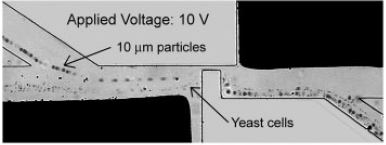
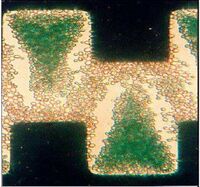
DEP technology has been used to separate a variety of different cell systems that include separating out bacteria, cancer cells, and viruses. Cells like particles have different electrical properties that include polarizability and net charge, which may be referred to as electrical phenotype [6]. The cell membrane/wall and cytoplasm contribute most to the cell’s overall induced charge. The first separation methods used the concept of negative and positive DEP. If cells have vastly different electrical properties then a frequency and a solution can be easily found where one type is forced towards the electrode and another away from the electrode. This method has been employed in a range of systems including the separation of viable cells from solutions, which uses a castell electrode design. Figure 3: shows the separation of deceased yeast cells. The dead cells which are stained green are raised off the plane with the living cells towards the electrode [11]. Fig 5 is a picture of a device that incorporates DEP into a microfluidic device where a side channel filled with buffer solution was able to sort viable and non-viable yeast cells without the need for another 3-D electrode fabrication step [12]. Similar methods have also been used in more complex systems, for example the separation of cells expressing the antigen CD34+ out of peripherial blood stem samples [13].
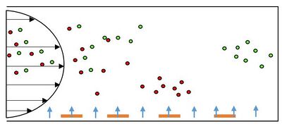
Separation is harder for cells with similar electrical properties. Techniques to separate these types of mixtures rely on the differences in magnitude of the CM factor. The primary way to separate cells using this method is called field-flow fractionation (DEP-FFF), which is shown in Fig 5 where there are a perpendicular and a parallel forces. The DEP force attracts one group of cells closer to the electrode then another in a parabolic flow channel, which enables one group of cells to go down the channel faster due to the differences in drag forces. One of the major benefits of this technique is that it is a one step process, unlike in techniques where cells have to be removed from specific electrodes. In essence, this method allows for the separation of closely related, complex cell mixtures [10]. There are also several limitations to this process. For smaller particles like viruses, Brownian motion comes into play and the pressure driven flow makes manufacturing these devices difficult.
Cell Handling
As shown above, electrode geometries can have a great effect on how to separate different cells. Initial devices were made out of sheets of metal. However one of the goals of current research is to lessen the voltage needed and these electrodes can be made through photolithography, laser ablation, and electron beam patterning [14]. Fig 3 represents one of the key geometries; there are areas of high and low forces which allow the particles to go through positive and negative DEP to settle. In addition to cell separation, devices are being made to trap and transport cells using DEP forces. The goal is to create an electrode design where there is zero net charge on the particle. Quadrupole electrodes have four electrodes with alternating voltage polarities applied to every other electrode to trap a particle. The video below shows insulating-post geometry where the insulating cyclical posts etched in a channel create field obstructions necessary for DEP [6]. There is a wide range of different research is being conducted to control the separation, pattern, and transport of cells.
<html> <iframe class="youtube-player" type="text/html" width="340" height="256" src="https://www.youtube.com/embed/Fw5aNdPBoBU" frameborder="1"></iframe> </html>
Other Applications
Although the most publications regarding DPS revolve around separation of cells, this process can be applied to any neutral particle. For example it has been shown that DEP can be used in metallic nanotubes separation and micro-structures assembly, which could have a large impact in the semi-conducting industry [14]. DPS is applied in the pattering, tapping and filtering of carbon nanotubes, nano-spheres, polystyrene, and silica particles. DPS is also being used in filtering and determining the concentration of crystallized proteins [15].
Future Outlook
DPS based systems are a candidate for a wide range of applications; many devices show a high level of control in micro level systems. The simplicity and low voltage characteristics may provide a future answer to carbon nanotube deposition controlling and point-of-care testing, which can replace bench top testing devices. [15]
References
[1] Pohl, H. A. Journal of Applied Physics 1951, 22 (7), 869–871. Doi: http://dx.doi.org.silk.library.umass.edu/10.1063/1.1700065
[2] Pohl, H. A.; Crane, J. S. Biophysical Journal1971, 11 (9), 711–727. Doi: http://dx.doi.org/10.1016/s0006-3495(71)86249-5
[3] Pethig, R. Journal of The Electrochemical Society 2016, 164 (5). Doi: http://dx.doi.org/10.1149/2.0071705jes
[4] Pethig, R. Biomicrofluidics2010, 4 (3), 039901. Doi: http://dx.doi.org/10.1063/1.3474458
[5] Hsu, T.-R. MEMS and microsystems: design, manufacture, and nanoscale engineering; John Wiley: Hoboken, NJ, 2008.
[6] Voldman, J. Annual Review of Biomedical Engineering 2006, 8 (1), 425–454. Doi:http://dx.doi.org/10.1146/annurev.bioeng.8.061505.095739
[7] Gascoyne, P. R. C.; Vykoukal, J. Electrophoresis 2002, 23 (13), 1973. http://dx.doi.org/10.1002/1522-2683(200207)23:13<1973::aid-elps1973>3.0.co;2-1
[8] Kadaksham, J.; Singh, P.; Aubry, N. Fluids Engineering 2003. Doi: http://dx.doi.org/10.1002/1522-2683(200207)23:13<1973::AID-ELPS1973>3.0.CO;2-1
[9]Ballantyne, G.; Holtham, P. Minerals Engineering 2010, 23 (4), 350–358. Doi: http://dx.doi.org/10.1016/j.mineng.2009.09.001
[10] Pethig, R.; Markx, G. Trends in Biotechnology 1997, 15 (10), 426–432. Doi: http://dx.doi.org/10.1016/s0167-7799(97)01096-2
[11]Markx, G. H.; Pethig, R. Biotechnology and Bioengineering1995, 45 (4), 337–343. Doi: http://dx.doi.org/10.1002/bit.260450408
[12]Suehiro, J.; Pethig, R. Journal of Physics D: Applied Physics 1998, 31 (22), 3298–3305. http://dx.doi.org/10.1088/0022-3727/31/22/019
[13]Talary, M. S.; Mills, K. I.; Hoy, T.; Burnett, A. K.; Pethig, R. Medical & Biological Engineering & Computing 1995, 33 (2), 235–237.Doi: http://dx.doi.org/10.1007/bf02523050
[14] Maria Dimaki and Peter Bøggild 2004 Nanotechnology 15 1095 http://dx.doi.org/10.1088/0957-4484/15/8/039
[15]Çetin, B.; Li, D. Electrophoresis 2011, 32 (18), 2410–2427. http://dx.doi.org/10.1002/elps.201100167
