Beauchamp:MotionCorrection
Beauchamp Lab wiki
|
Motion Correction
Over the ~hour-long course of a typical fMRI experiment, it is impossible for the subject's head to remain in the same position, barring the use of uncomfortable restraint hardware such as bite bars. For compliant subjects, the head motion usually consists of a gradual motion as the chin sinks towards the chest or the entire head sinks into the cushioning foam.
Here is a graph showing head position and rotation in a typical fMRI experiment with a compliant subject (case CW). The x-axis represents time. Each time-point represents one EPI image, and each graph shows the amount of shift or rotation estimated to have occurred at that time point by the AFNI program 3dvolreg:
It is not possible to fully correct head motion. If data about a spatial location was not acquired, no algorithm will bring it back. However, the effect of movement can be minimized. The usual approach is to simply shift and rotate each image to match a template.The template can be either the mean of all EPI images, or a single EPI image, usually the EPI image collected closest in time to the high-resolution anatomical T1 dataset (see below). A good qualitative way to examine motion and the efficacy of motion correction is to open axial, sagittal and coronal views of the EPI dataset. Switch back and forth between the 0th timepoint and the last timepoint, using the arrows next to the "Index" label inside the main AFNI window.
Distortion Correction
EPI images are significantly distorted relative to true brain anatomy.
This is a problem because activation maps created from EPI images are overlaid on T1 images (or cortical surface models created from T1 images) which reflect the true anatomy.
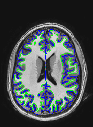
The following images show a T1 image with outlines for the outer boundary of gray matter (blue line) and white matter (green line).
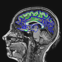
Here are uncorrected EPI images with the same boundaries overlaid.
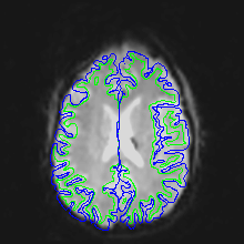

Note that this is not a problem of subject motion: inhomogeneities in the magnetic field in the head (create by the tissue properties) creates the distortion. The best way to remove distortion is to measure the magnetic field in the scanner (creating a B0 map) and use it to unwarp the EPI images. Because this is not commonly done, a second choice is to distort the EPI images so that they match the T1 image. This is done in AFNI using the 3dAllineate program.
Cropping the Anatomical Image
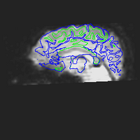
EPI images usually do not cover as much anatomy as the anatomical. In the sagittal images above, the T1 images cover the skull, jaw and neck, while the EPI images do not. Stretching the EPI images to match the T1 image would make the distortion worse, not better. Therefore, the first step is to skull-strip and crop the anatomical image so that it covers the same volume of tissue as the EPI volume. Here are AFNI commands to do this:
 set ec = subject_name
 3dSkullStrip -input  {$ec}anatavg+orig -prefix {$ec}anatavgSS
 3dresample -master {$ec}r1+orig -dxyz 1.0 0.938 0.938 -inset {$ec}anatavgSS+orig -prefix {$ec}anatavgSScrop
Where r1 is an EPI dataset and anatavgSS is the skull-stripped T1. Note the values after -dxyz are not critical; we simply want to maintain the original high resolution of the T1 anatomy (usually ~1 mm). Here we have chosen the values to be exactly the same as the original voxel size of the T1.
Here is the cropped anatomical:

When 3dSkullStrip fails to give a good skull stripped brain, work backwards from the FreeSurfer cortical surface to a skull stripped brain for AFNI using 3dSurfMask and 3dcalc. We want to use the pial surface and do each hemisphere separately, as 3dSurfMask cannot do multiple surfaces at once. Once we have a mask, we want to multiply by the appropriate anatomy (the same anatomy that serves as the grid_parent in the 3dSurfMask command). Here are some sample commands:
  3dSurfMask -i_fs lh.pial.asc -prefix {$ec}FSskullstriplh -grid_parent {$ec}anatr1+orig -sv {$ec}_SurfVol_Alnd_Exp+orig
  3dSurfMask -i_fs rh.pial.asc -prefix {$ec}FSskullstriprh -grid_parent {$ec}anatr1+orig -sv {$ec}_SurfVol_Alnd_Exp+orig
  3dcalc -prefix {$ec}goodSS -a {$ec}FSskullstriplh+orig -b {$ec}FSskullstriprh+orig -c {$ec}anatr1+orig -expr
  'c*step(ispositive(a)+ispositive(b))'
If you want to talairach this stripped brain, make sure that it approximates the template you use. For instance, if you use TT_icbm452+tlrc, what we make from FS is off due to its lack of inclusion of the cerebellum and brainstem. In this case, you might see what 3dSkullStrip buys you in terms of those unincluded elements and add it to what you get from FS. Here are some sample commands:
  3dSkullStrip -input  {$ec}anatr1+orig -prefix test1 -push_to_edge
  3dcalc -prefix {$ec}goodSSv2 -a {$ec}FSskullstriplh+orig -b {$ec}FSskullstriprh+orig -c test1+orig -d
  {$ec}anatr1+orig -expr 'd*step(ispositive(a)+ispositive(b)+ispositive(c))'
  @auto_tlrc -base TT_icbm452+tlrc -no_ss -input {$ec}goodSSv2+orig
  adwarp -apar {$ec}goodSSv2_at+tlrc -dpar {$ec}anat_Alnd_Exp_w_Elec+orig
Removing Distortion and Motion Correction in one step
Because shifting and scaling degrades the image, we perform motion correction and distortion correction in one step. Here are sample commands to do this:
  3dAllineate -base {$ec}anatSScrop+orig -1Dmatrix_save t2EPI_to_T1.aff12.1D -input {$ec}t2+orig'[0]'  -EPI -cost mi
  3dvolreg -prefix NULL -1Dmatrix_save t2EPI_to_EPI.aff12.1D  -base {$ec}t2+orig'[0]'  -input {$ec}t2+orig  -1Dfile {$ec}t2vr.1D -cubic
  cat_matvec t2EPI_to_T1.aff12.1D t2EPI_to_EPI.aff12.1D > t2allEPI_to_T1.aff12.1D
  3dAllineate -master {$ec}anatSScrop+orig -mast_dxyz 2.0 -1Dmatrix_apply t2allEPI_to_T1.aff12.1D -input {$ec}t2+orig -final quintic -prefix {$ec}t2Al
Whereas the above aligns all EPIs to the first EPI ({$ec}t2+orig'[0]'), we can instead align to the mean EPI, which actually produces a slightly better F ratio for a given voxel. First, measure motion in each run separately, perform the registration, and save motion parameters. Create the mean EPI:
  3dTcat -prefix {$ec}rall {$ec}r1+orig.HEAD {$ec}r2+orig.HEAD {$ec}r3+orig.HEAD {$ec}r4+orig.HEAD {$ec}r5+orig.HEAD {$ec}r6+orig.HEAD {$ec}r7+orig.HEAD {$ec}r8+orig.HEAD
  3dTstat -mean -prefix {$ec}EPImean {$ec}rall+orig.HEAD
Next, we can either simply perform registration of each run to the same mean image:
  foreach r (1 2 3 4 5 6 7 8)
     3dvolreg -prefix {$ec}r{$r}vr -base {$ec}EPImean+orig  -input {$ec}r{$r}+orig  -1Dfile {$ec}r{$r}vr.1D
     -cubic
  end
Or, we can both register the EPIs to the same mean image AND allineate each run to the hi-resolution anatomical image (see motion correction page):
  3dAllineate -base {$ec}anatSScrop+orig -1Dmatrix_save {$ec}EPI_to_T1.aff12.1D -input  {$ec}EPImean+orig -EPI -cost mi
  foreach r (1 2 3 4 5 6 7 8)
     3dvolreg -prefix NULL -1Dmatrix_save {$ec}r{$r}EPI_to_EPI.aff12.1D -base {$ec}EPImean+orig  -input
     {$ec}r{$r}+orig  -cubic
     cat_matvec {$ec}EPI_to_T1.aff12.1D  {$ec}r{$r}EPI_to_EPI.aff12.1D >  {$ec}r{$r}EPI_to_EPI_to_T1.aff12.1D
     3dAllineate -master {$ec}anatSScrop+orig -mast_dxyz 2.0 -1Dmatrix_apply
     {$ec}r{$r}EPI_to_EPI_to_T1.aff12.1D -input  {$ec}r{$r}+orig  -final quintic -prefix  {$ec}r{$r}vr+orig
  end
First, we measure the amount of distortion correction needed with 3dAllineate; then we measure the motion correction needed with 3dvolreg; then we combined the two transformations; then we apply the transformation.
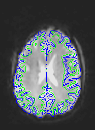
A qualitative way of judging the effectiveness is to overlay the unwarped EPI on the T1 and see how they match.
Here are corrected EPI images with the gray and white matter boundaries overlaid.
Measuring the effectiveness of motion and distortion correction
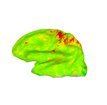
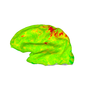
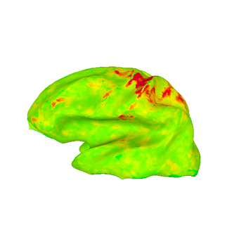
A quantitative way to judge the effectiveness of motion and distortion correction is to analyse fMRI activation maps created from EPI data; if motion and distortion correction is successful, the significance of the observed activation should, in general, be higher. For the sample dataset above (case CW) here is the F-statistic of the most significant voxel:
No motion or distortion correction: peak F = 8.91
No motion correction, distortion correction applied independently to every image:peak F = 8.88
Motion but not distortion correction: peak F = 9.11
Motion and distortion correction (as above, motion corrected to EPI image closest in time to anatomy): peak F = 9.76
Motion and distortion correction (motion corrected to mean EPI image): peak F = 9.86
These images show lateral views of surface models. The colors represent the F-statistic at each surface node for each of the motion and distortion correction methods. While there are differences between the images, they are subtle.

