BME100 s2015:Group9 12pmL6
| Home People Lab Write-Up 1 | Lab Write-Up 2 | Lab Write-Up 3 Lab Write-Up 4 | Lab Write-Up 5 | Lab Write-Up 6 Course Logistics For Instructors Photos Wiki Editing Help | ||||||
|
OUR COMPANY
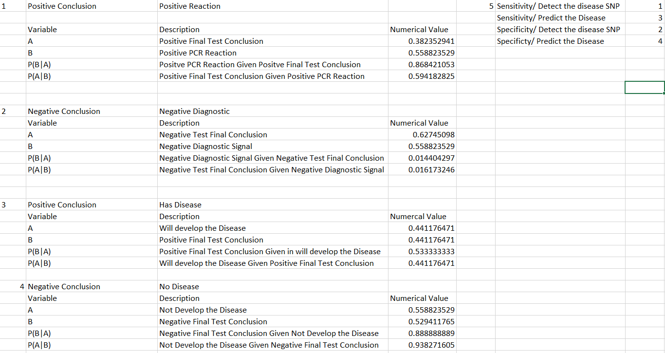
Lelouch of Fate Zero Dynasty LAB 6 WRITE-UPBayesian StatisticsOverview of the Original Diagnosis System For this experiment, 68 patients were tested for a disease via a disease-associated SNP. These patients were asked for two samples each of their DNA. The DNA sample pairs were kept together, and a number that was associated with the patient was attached to them. These pairs were distributed amongst 34 teams for testing, amounting to two subjects or four DNA samples per team. The reason for asking each patient for two samples of DNA is to prevent error. That requirement, along with other steps, assures that any anomalies in a single sample will not skew an entire data set. Also, the results from a single patient's samples can be compared to each other and conclusions can be drawn concerning the validity of the test based on the similarity in their results. This is same reasoning behind using multiple drops of DNA solution from each individual sample. Other actions taken to reduce error include positive and negative controls, and the precision of using ImageJ. Adding positive and negative controls established a baseline range for our results, and allowed for direct comparison analysis. This comparison was completed by ImageJ software. The pixel color analysis feature on ImageJ allowed for more accurate, mathematical results as compared to, say, teams visually comparing the color the images side by side. These precautions were necessary to accurately analyze the validity of the chosen test using Bayesian statistics.
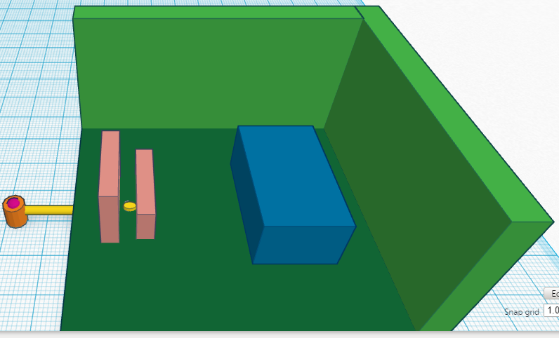
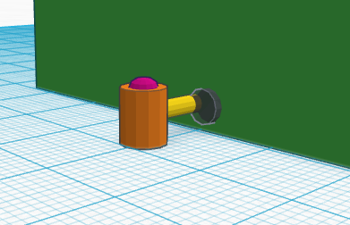
Computer-Aided DesignTinkerCAD The TinkerCAD tool was used in creating a 3D design of the fluorimeter setup. On a square platform three objects were created representative of a stand for phone/camera (in pink) and fluorimeter light (in blue). The base was placed four centimeters away from the fluorimeter light. A three millimeter cut was made in the bottom of the box at the phone stand and ran to the edge of the box. A cylinder was drawn leading up to the base of the box to represent a USB cable (in yellow). The USB cable was then attached to a button device (in orange) outside of the box for controlling the camera device. The box was created with a cross-sectional cut of the box to allow for viewing the inner contents.
Fluorimeter Box-Green The chosen design was similar to the basic fluorimeter setup. This included a phone base placed four centimeters away from the fluorimeter light placed within a box. A cut was made at the bottom of the box to allow a cord to pass through. This design was chosen for greater simplicity and ease of use of the typical fluorimeter design. This aids in completing the intended use more efficiently and in less time. The differences in the designed fluorimeter setup include an anchored base and fluorimeter light to always allot for proper positioning of the pictures at a four centimeter distance. The cut at the bottom of the box will allow a cord to adapt to the phone/camera device for external imaging of the specimen.
Feature 1: Consumables KitThe liquid reagents and mixing fluids will be packaged within their respective tubes which can be labeled easily with any writing utensil. Both the tips for the micropipettor and the tubes containing SYBR Green liquid will be tinted black in order to reduce the affect of light interacting with the SYBR Green liquid, which is highly light-sensitive. All consumables will be packaged in small containers that can be shipped conveniently.
Feature 2: Hardware - PCR Machine & FluorimeterThe PCR machine will be a closed box with a door that pops off from one side of the machine. This sealed door will keep out the maximum amount of light while the fluorimeter is in use. Inside the box, indentations have been added to the bottom of the box that are meant to hold the fluorimeter and the cell phone stand at the standard 4 cm away from each other. This modification ensures that each picture will be taken at the exact same distance from the droplet. The other addition to the system is a mechanism that will allow the experimenter to take the picture from outside the box, eliminating the need to open the door and let light in when the picture is taken. This mechanism consists of a wire that runs from inside the box to outside from the bottom panel. On the inside, a port that is compatible with most phones extends into the cell phone stand. On the outside of the box, it connects to a trigger button whose only fucntion is to access the phone's camera and take a picture.
| ||||||


