20.109(F07): ECD assembly
Introduction

Just in time for the holiday shopping season, Amazon.com came out with a wireless reading device called the “Kindle.” Since the Kindle devices are in high demand, we’ll have to wait until the stock is replenished to see all the aspects of this “revolution in book reading.” The promotional material for this handheld book-sized product states, “unlike computer monitors, the Kindle’s electronic ink display reads like real paper.” The device has other selling points like the low cost for NYTimes best sellers, the speed and ease with which content can be updated, and the device’s battery life and weight. However it’s the display that we’ll focus on here.
In principle, there’s a lot about the Kindle’s electronic paper that beats other electronic display technologies. When you consider the workings of modern computer monitors or plasma TVs (as you did in your FNT assignment on the first day of this module), you note how their workings rely on excitation of a material held in tiny cells between panels of glass. The excited materials emit light of particular wavelengths and the image that’s generated is as sharp as the cells are small and can change as fast as the light can vary. By contrast if you read a book rather than watch TV, the pages change only as fast as you can turn them and your eyes get less tired since they are not bombarded with energy from the excited and emitted light. The book’s lettering absorbs some of the ambient light and we perceive the light that’s reflected. Thus, in a perfect world, electronic paper would reflect rather than emit light from its display and would rapidly update what’s shown, turning the pages of your book faster than you can. Ideally electronic paper could find other useful niches, like realizing a Marauder’s map from the Harry Potter book series, in which a person’s location is updated on the map in real time display.

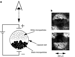
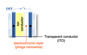
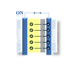
The speed with which a display’s image can update is dependent on the rate at which each pixel can toggle, a response that depends on the nature of the pixel. In plasma or liquid crystal displays, it’s a physical material that changes its properties when it reacts with light. These sorts of molecular reactions are lightening fast. In the case of the Kindle, its images are generated by spherical microcapsules that are black on one side and white on the other. As these microcapsules flip-flop in a field, the display is updated pixel by pixel, but only as fast as the spheres can physically rotate in space. For the electrochromic device we are building in lab, the color change is a result of a redox reaction on the iridium oxide. The phage nanowires are purple/grey in their oxidized state but transparent when an electron is added from the surrounding conductive material. A positive counterion, in our case lithium, comes from a surrounding electrolyte solution that is needed to balance the electron’s negative charge. The contents of the lithium electrolyte solution are described in more detail below. Redox reactions are very fast and so in principle, the switch time of the IrO2 display is on par with any chemistry-based device. However there are three confounding factors that reduce the responsiveness on the iridium oxide wires: hydration, optical contrast and electrolyte diffusion.

If water is present, hydrating either the layer of nanowires or the lithium electrolyte solution, then a competing reaction must be considered. In this reaction, the iridium oxidation state is unchanged and the redox state of the lithium ions react with water to give LiOH and a proton. Thus, water is expected to direct the redox potential into side reactions with the lithium itself and draw down the display’s contrast. To avoid this problem water must be evaporated from your ITO-phage patterned slide before the electrolyte solution can be added, and the solution itself should be prepared in organic rather then aqueous solvents.
Optical contrast is also affected is the irregular packing of nanowires on the ITO surface. The application of the phage nanowires to the patterned ITO was driven by charge and consequently is distributed unevenly. Some areas of the ITO will have clumps or tangles of nanowires and other areas of the slide have few to none. Further engineering of the phage or the application process will be needed to yield a more even surface of nanowires to maximize contrast of the device.
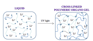
While water and packing of the nanowires affect the optical contrast of the device we are building, the switch speed of the device is limited by diffusion of the electrolyte. The lithium ions take a random walk to the reduced iridium oxide, and this walk can be accelerated by “caging” the path using some crosslinked materials. Some electrolyte solutions are infused in a porous membrane. Others are made in solid polymers. The solution we will use for our devices is an organogel. The choice of polymer to house the electrolyte, as well as its concentration and when applicable crosslinking ratio, is a critical one since the nature of the polymer solution can dramatically affect the electrochemical stability and mechanical properties of the device. All need high ionic conductivity to allow mobility of the lithium ions as well as transparency so the device has only one color-generating material.
Protocol
Part 1: Phage titers for M13.1 and MDS
Record the number of plaques for each plate you prepared last time, and then use the most "countable" to calculate PFU/ml for the M13K07/M13.1 and WT/MDS pairs. To collect the class's data in one place, you should then copy two tables to the data collection page. Since we might want to publish this class data in a peer reviewed journal, it will be particularly important for you to provide complete and accurate information as well as for you to "sign" your work so we can attribute you properly. You should also write a summary paragraph for this experiment to include in your lab notebooks. Propose an experiment or two that you might try as follow up if 20.109 didn't have to end.
Plaque numbers
| phage = M13K07, strain = MG1655 | phage = M13K07, strain = MDS | phage = M13.1, strain = MG1655 | phage = M13.1, strain = MDS | |
| 10-6 | ||||
| 10-8 | ||||
| 10-10 |
Titer
| phage = M13K07, strain = MG1655 | phage = M13K07, strain = MDS | phage = M13.1, strain = MG1655 | phage = M13.1, strain = MDS | |
| titer (PFU/ml) |
Part 2: Li overlay
- Examine your dried pattern. If there are any patches of IrO2 nanowires deposited on the non-ITO part (i.e. the part that was etched away during the acid wash), you can carefully remove them using a cotton-tipped applicator that is damp with methanol. Be very careful as you do this because you could easily ruin your pattern.
- Place both slides into a 50°C oven for at least 20 minutes to fully evaporate any water that is on them. (Not crucial for 20.109 lab.)
- Before you begin mixing the electrolyte solution, you’ll need to clean a 20 mL scintillation vial. To do this you’ll want to blow out any dust that is in the vial with house air or nitrogen (or a high pressure air bottle).
- Begin making polymer electrolyte solution by dissolving 1 g of electrolyte salt into 7.5 g of solvent in your 20 mL scintillation vial. It may be difficult the dissolve the salt. To speed up the process, put a small magnetic stir bar into the vial. Put the vial onto a stirring/heating plate and heat the solution while stirring until the salt is fully dissolved. Once it is fully dissolved, turn off the heat.
- Add 1.5 g of the monomer solution to the solution from the previous step and stir until mixed.
- To make the initiator solution, add 70 mg of the initiator to 1 g of the solvent in a 2 mL microfuge tube. Vortex until fully mixed. Spin the tube in a microcentrifuge and add the solution to the monomer/electrolyte solution. Mix fully by vortexing or by spinning on spin plate. The initiator is light sensitive, so try to move quickly. Once the solution is fully mixed, wrap the entire vial in tin foil to protect it from light.
- Remove the plastic covers from the silicon septum. Carefully lay the septum on the ITO side of the patterned slide so that your pattern is fully enclosed by the septum. Note that the septum is larger than the pattern and that some of the unpatterned portion of your slide also will be enclosed by the septum. If you’d like to get really fancy, you can trim the septum down so that you end up with a square of septum that is exactly the size of your pattern (this is not necessary, though).
- Make sure that the septum is fully sealed to the slide at all points, so that nothing can leak out between the septum and the slide.
- Open the vial with the monomer electrolyte solution. Using a 1 mL micropipette, add ~700 uL of the solution to the space on top of the slide that is surrounded by the silicon septum. Add this solution slowly and try to evenly disperse it across the slide. Do not allow any bubbles to form. Do not worry about completely covering the slide – when you add the second slide to the top it should spread out the polymer solution.
- Put the second ITO slide (ITO side facing the septum) onto the patterned slide / silicon septum stack. When you add it, make sure that the overhanging end (the end not covered by the septum) is not on the same side of the slide as the overhanging end from the patterned slide (see figure). We will need to hook up both slides to different electrodes and if the two overhanging ends are facing each other, it will be very difficult to do this.
- Carefully wipe off any of the polymer electrolyte that has leaked out of the sandwich.
- Place the ECD sandwich into a plastic Petri dish. Next to the sandwich put a small dab of the polymer solution (you can use this dab to check for solidification of the polymer). Place the Petri dish onto a UV irradiation box for at least 10 minutes. This will activate the initiator and the polymer solution will form a solid gel. NOTE: NEVER EXPOSE YOUR EYES OR SKIN TO THE UV LIGHT.
- Gently test to make sure that the polymer solution has hardened. If it has, then remove the ECD from the UV irradiation box and use some epoxy to seal the edges of the device. Try to seal all of the septum / slide connections. Place the sealed device into a 50°C oven for 5-10 minutes until the epoxy has cured.
- Remove the ECD from the oven. It is now finished and ready for testing!
- If you’d like, you can clean the glass surfaces of your device with a cotton applicator that is damp with methanol. You can also try to use a razor blade to trim any excess epoxy. Be careful as you do this, because the slides can crack if you use too much force.
- You can test the ECD by hooking up your battery box to it. Use the alligator clips to hook the positive electrode to one end and the negative electrode to the other end.
- IrO2 film hooked to positive = oxidation = removing Li+ from IrO2 film = absorbs light = appears dark
- IrO2 film hooked to negative = reduction = pulling Li+ onto IrO2 film = clear
For next time
Prepare a 10 minute powerpoint talk that describes the research question you have identified, how you propose to study the question and what you hope to learn. More detailed descriptions of the elements of the oral presentation can be found in the FNT assignments and the protocols associate with this Module as well as with the research proposal guidelines. When it is ready, please email your presentation to nkuldell AT mit DOT edu or astachow AT mit DOT edu. Speaking order will be determined by the order that presentations are received.
On the day you present (see announcements on front page for when and where) your team should print out and bring three copies of your powerpoint slides. Black and white is fine and you can print more than one slide per page if you like. You should also write and print out your "talking points" into the comments box of each of the slides you'll present. These are speaking notes for your presentation. They should include the words you'll use to describe each slide and the transitions you've planned between them. For example from last year's presentations, one slide's talking points were:
"Slide shows normalized data (we took logs)
- Red color used for down regulated genes
- Lime green for upregulated
- Olive green used when nothing changed
We dictated what would be considered “Nothing” by putting them into bins Arbitrarily assigned ‘nothing’ as anything between -1 and 1, because it could just have to do with background and the such
Note many open reading frames and hypothetical proteins
Now let’s look at each component individually!"
You will be graded on the integrated success of your presentation: concepts, slides, talking points, and presentation.
