Valve Multiplexing - Megha Shah
Introduction
Multiplexing is often used to convert multiple analog or digital input signals through common transmission lines to an output. A multiplexer (or multiplexor) is a device consisting of a combinational logic circuit that switches a particular input to a common output using a control signal. Multiplexers are rapidly changing rotary switches that connect multiple different input channels to an output line one at a time.
VSLI Technology
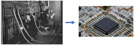
The first transistors, introduced in the 1900s, were initially made of vacuum tubes as shown to the left in Figure 1.[1] They were too large and cumbersome to be integrated into circuits such that typically less than 10000 transistors could fit on a chip. However, in 1947, Dr. John Bardeen, Dr. Walter Houser Brattain, and Dr. William Bradford Shockley, Jr. invented the first germanium based semiconductor transistor, which was considered a remarkable breakthrough in the development of solid-state electronic devices. The widespread use of semiconductor transistors led a revolution in the electronics industry, further giving rise to LSI (large-scale integration) and VLSI (very large scale integration). An example of a modern chip is given to the right in Figure 1.[2] Nowadays a VSLI chip can go up to 10 billion transistors with feature sizes smaller than 15 nm.[3]
Multiplexing Valves in Microfluidics
Similar to an electronic chip, with the increasing density of chambers on microfluidic chips, the number of micromechanical valves needed to manage them can easily go as high as hundreds and thousands. The operational cost of building and integrating thousands of connecting tubes can become quite expensive. Moreover, such complex circuits could be very difficult to scale up. Not to mention, troubleshooting a problem with thousands of valves and connections would be extremely time-taking and inefficient. Valve multiplexing systems, similar to electronic integrated circuits, are developed to allow complex fluidic functions with a minimal number of inputs. Valve multiplexing has many biological applications such as biomolecular separations, enzymatic assays, and polymerase chain reactions. All of these applications are a scaled-down version of current technology in the form of an integrated circuit. Mass production via scaling down is a relatively new idea and it poses many advantages by saving expense, space, and labor.[4]
Binary Multiplexor
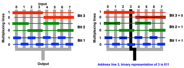
Microfluidic multiplexors are combinatorial arrays of binary valve patterns that reduce the number of inputs, thus increasing the processing power of a network. A multiplexor is analogous to a binary tree in which [math]\displaystyle{ n }[/math] fluid channels can be controlled with only [math]\displaystyle{ 2log_2n }[/math] control channels. The power of such a binary network is evident in the fact that 1024 flow channels can be controlled by only 20 control channels.
As shown in Figure 2, the grey lines are input lines all connected to one output. The colorful multiplexing lines are hydraulically actuated to control which input lines make it to the output. Valves form at the intersection of the wide part of the multiplexing lines with flow lines because it requires higher pressure to actuate thinner lines than thicker. The actuation pressure that is applied is high enough to deflect the wide parts, but it is too low for thinner parts to actuate. In order to select a particular channel, a combination of open and closed valves based on the binary system is employed. Each pair of multiplexing lines is arranged in the form of a bit with an alternating pattern of thicker and thinner parts as shown in Figure 2. For example, a binary combination of 011 has to be selected to connect only channel 3 to the output. Actuating the multiplexing line corresponding to bit3 = 0 closes off input lines 4-7, bit2 = 1 closes off lines 0 and 1, and bit1 = 1 finally closes off line 2, leaving only channel 3 open.
Thorsen et al. developed multiplexors containing two distinct layers: a control layer and a flow layer. The control layer consists of all the channels responsible for actuating valves, and it is located on top of the flow layer, which involves a network of channels being controlled. Fluid manipulations and biological assays are performed in the flow layer. The intersection of a control channel and flow channel creates a valve in which the thin membrane between the two channels can deviate through hydraulic actuation. This approach is applicable to any pneumatically controlled valve regardless of its position, whether it be the top or bottom layer.[4]
Ternary and Quaternary Multiplexer
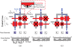
In binary multiplexers, all of the valves are actuated with the same pressure, therefore they use [math]\displaystyle{ n }[/math] lines to address [math]\displaystyle{ 2^{{(n/2)}} }[/math] flow channels. However, ternary and quaternary multiplexers address multiple flow channels with fewer control lines by having valves with varying pressure thresholds. Ternary (two kinds of valves) and quaternary (three kinds of valves) multiplexers can address [math]\displaystyle{ 3^{{(n/2)}} }[/math] and [math]\displaystyle{ 4^{{(n/2)}} }[/math] flow channels respectively. It is known that a wide channel has a low actuation threshold, thus it requires less pneumatic pressure to close flow channels compared to a narrow channel as shown in Figure 3. Therefore, the dimensions of the valves are varied to achieve multiple actuation thresholds.[5]
Multiplexer for Non-Pneumatic Valves
pH-Controlled Valves
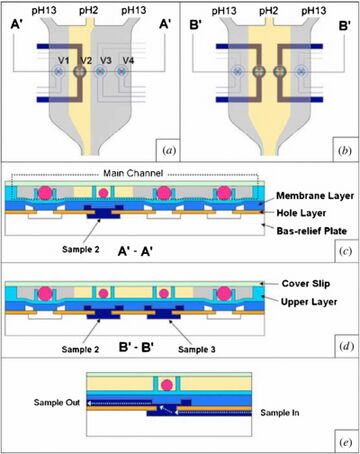
The actuation of pneumatic valves involves the use of bulky pumps and electronic apparatus. To overcome this problem, Lee et al. proposed pH actuated valves. The team developed a microvalve array based on pH-responsive hydrogel beads that are controlled by the laminar streams of multiphase pH solutions. The device consists of four layers: an upper layer, a membrane layer, a hole layer, and a bas-relief layer. The upper layer consists of the main channel where staged hydrogel beads are controlled by pH buffers. Two main buffers of pH 2 (yellow) and pH 13 (grey) are used. The beads expand in a basic solution and impose pressure on the membrane layer that closes the hole. However, in an acidic solution, the bead contracts, restoring the membrane layer. The hole is open and the sample flows through the hole layer as shown in the Figure 4. The opening and closing of particular valves are executed by controlling the flow rates of the pH solutions. Since the laminar flow is maintained, both buffers flow next to each other without mixing. As shown in Figure 4, at a low flow rate, the acidic buffer flows only through one lane. With an increase in the flow rate the adjacent lane is also covered with acidic buffer.[6]
Shape Memory Actuators
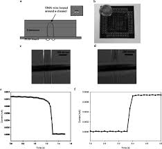
The difficulty with the shrinking of pneumatic solenoids, tubing, and mechanical pins is an impedance to developments in the miniaturization of microfluidic circuits. Shape memory alloys (SMAs) are materials that can be deformed at low temperatures, but when heated they return to their original shape. Vyawahare et al. combined SMAs with multilayer soft lithography to integrate microfluidic elements like valves, pumps, multiplexers, etc. at a smaller order of magnitude. As shown in Figure 5, an SMA wire is wrapped around the flow channel and soldered to a PCB board embedded in PDMS. The wire is heated resistively by applying a current, causing the wire to contract and squeeze the channel shut.[7]
Multiplexing of Pumps
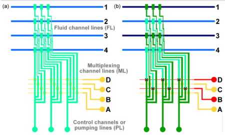
Multiplexing of pumps can simplify the complex pneumatic connections needed for the operation of peristaltic pumps. It allows control over a large number of pumps by a limited number of external pneumatic connections. Thus, instead of needing [math]\displaystyle{ N_{{pumps}} }[/math] x [math]\displaystyle{ N_{{valves}} }[/math] connections, multiplexing needs only [math]\displaystyle{ N_{{pumps}} }[/math] + [math]\displaystyle{ N_{{valves}} }[/math] connections. In Figure 6, the blue flow lines, each controlled by a peristaltic pump, are connected to multiple flow lines (in green). The individual flow lines are in turn controlled by binary multiplexing lines (in yellow).[8]
References
- Swirski, P. From Literature to Biterature. https://www.mqup.ca/blog/literature-biterature/ (accessed 2024-03-10).
- Mitul. Moore’s Law & VLSI Fabrication Techniques. https://mitul18.medium.com/moores-law-vlsi-fabrication-techniques-58e20b0a0c38 (accessed 2024-03-10).
- Pillarisetty, R. (2011). Academic and industry research progress in germanium nanodevices. Nature, 479(7373), 324-328. DOI: 10.1038/nature10678
- Thorsen, T., Maerkl, S. J., & Quake, S. R. (2002). Microfluidic large-scale integration. Science, 298(5593), 580-584. DOI: 10.1126/science.1076996
- Lee, D. W., & Cho, Y. H. (2009). High-radix microfluidic multiplexer with pressure valves of different thresholds. Lab on a Chip, 9(12), 1681-1686. DOI: 10.1039/B820582E
- Liu, C., Park, J. Y., Xu, Y., & Lee, S. (2007). Arrayed pH-responsive microvalves controlled by multiphase laminar flow. Journal of Micromechanics and Microengineering, 17(10), 1985. DOI: 10.1088/0960-1317/17/10/009
- Vyawahare, S., Sitaula, S., Martin, S., Adalian, D., & Scherer, A. (2008). Electronic control of elastomeric microfluidic circuits with shape memory actuators. Lab on a Chip, 8(9), 1530-1535. DOI: 10.1039/B804515A
- Cole, M. C., Desai, A. V., & Kenis, P. J. (2011). Two-layer multiplexed peristaltic pumps for high-density integrated microfluidics. Sensors and Actuators B: Chemical, 151(2), 384-393. DOI: 10.1016/j.snb.2010.07.012
