User:Joseph Frye/Notebook/Physics Junior Lab 307L/e/m
Steve Koch 04:53, 21 December 2010 (EST):Good primary lab notebook.
E over M ratio
This lab was performed in the junior laboratory in the UNM physics building on October 11, and October 18 with Alex Benedict
Links
Equipment and Setup
We followed the setup and procedure for this lab in Dr. Gold's lab manual, experiment number 2
Equipment
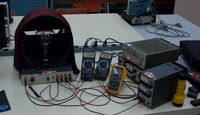
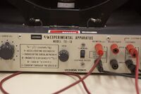
- e/m Experimental Apparatus Uchida model TG-13
- 3 Power supplies
- Gelman Deluxe, 6-9V 2A
- Soar DC PS 3630, 6.0V 1.5A
- Hewlett Packard 6236B, 150-300V 40mA
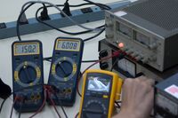
- 3 Digital Multimeters
The equipment was set up already when we began this lab. We used Dr. Gold's lab manual to check the connections and confirm that everything was hooked up properly.
Procedure and Data
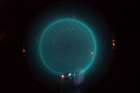
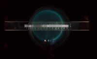
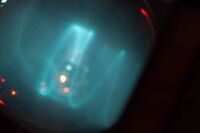
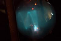
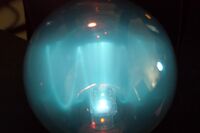
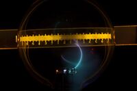
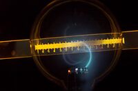
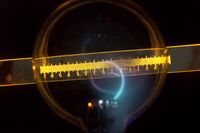
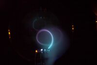
Inside the sealed bulb is an electron gun and helium gas. The bulb is in the center of Helmholtz coils which produce a magnetic field. A beam of electrons shoots from the gun into the bulb and the magnetic field curves the beam into a circle. We are able to measure the radius of the circle with a ruler on the back of the apparatus. By measuring the radius of curvature as we vary the accelerating voltage of the electron gun and the current supplied to the coils we are able to calculate the ratio of the electron charge(e) over the electron mass(m). According to the equation given on the front of the apparatus: [math]\displaystyle{ e/m=(2*V)/(B^2*r^2) }[/math]
The idea is that if we know the radius of curvature then we know [math]\displaystyle{ F/m=a }[/math] and we know the strength of the magnetic field and the kinetic energy of the electrons we can find the force as a function of the electron charge [math]\displaystyle{ F=e*vXB }[/math]
We vary the current in the coils to change the magnetic field. We vary the accelerating voltage to change the kinetic energy of the electrons.
DAY 1: We ran two trials today. The first trial we kept the current to the coils constant at 1.5A (constant B field) and varied the accelerating voltage from about 175V to about 225V in steps of 25V. We then measured and recorded the radius of curvature in a google docs spreadsheet. The second trial we kept the accelerating voltage constant at 200V and varied the current to the coils from 1.5A to 2.0A and again measured and recorded the radius of curvature. our data is hereFile:Benedict Frye E M ratio.ods
after looking at the data we had a relative error of about 23% which according to Dr. Koch is normal for this experiment with this e/m apparatus. We spent the rest of day 1 discussing why there would be so much error in the experiment. We varied the voltage and current some more and noticed some strange things.
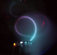
- In the lab manual the beam is supposed to be violet, ours was green. however at low accelerating voltages we are able to get portions of the beam to be violet.
- The filament voltage should not affect the radius of curvature but it does change the radius quite a bit
DAY 2:
we spent day 2 taking photos for the lab report and again trying to figure out why there is so much error in this experiment. We also tried to figure out why the beam is not violet but is instead green. Our observations are recorded on tab 2 of the included spreadsheet.
Results
I chose to analyse the two trials separately. The analysis is also in the spreadsheet.
Trial 1: Constant B field varying accelerating voltage
average e/m: 2.10899636048x10^11
Standard error of the mean 2.319917067*10^9
relative error 0.20
Fractional Error 0.01
Trial 2: Constant accelerating voltage varying B field
average e/m 2.23800140795x10^11
Standard error of the mean 1.453092519x10^9
relative error 0.27
Fractional Error 0.01
Accepted Value C/kg 1.75882017x10^11
