User:David K. O'Hara/Notebook/physics 307 lab/speed of light
Objective
SJK Incomplete Feedback Notice

My feedback is incomplete on this page for two reasons. First, the value of the feedback to the students is low, given that the course is over. Second, I'm running out of time to finish grading!
The objective of this lab is to measure the speed of light, one of the most fundamental physical constants. We will do this by generating a short pulse of light and then using a high speed detector to determine the direct time-of-flight (TOF) using distances between one to two meters long.
Equipment
Tektronix TDS 1002 oscilloscope
Canberra NSEC delay 2058
Bertan 313b power supply
EG@G Ortec 547 TAC/SCA Module
Harshaw nq-75 NIM bin
Harrison Laboratories 6027a power supply (for LED)
Led
Photomultiplier Tube (PMT)
Safety
Several of the electrical components run at high voltage and care should be taken with all instruments to make sure that no one is exposed to the danger of electrical shock.
Care must be taken to ensure that the photomultiplier tube is not exposed to room light while high voltage is applied. This could fry the PMT and will not improve experimental results.
Procedure
I connected the test equipment in the following manner. I ran a cable from the "-HQ" connection on the back of the PMT to the back of the Bertan power supply. The "A" connection on the PMT to the top input of the delay module. I connected the output of the delay module to a BNC T-splitter, with one side connected to channel 1 on the oscilloscope, and the other going to "Stop" input of the TCA. I connected the "Start" input of TCA to the cable attached to the LED. I connected the power cable for the LED to the power supply. Last, I connected the output of the TCA to channel 2 of the oscilloscope.
-
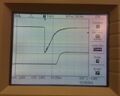 oscilloscope display of both lab signals
 -
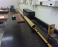 speed of light exp. setup
 -
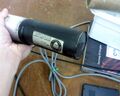 photomultiplier tube
 -
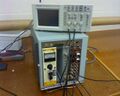 tac and power supply


Measurements were taken by placing the LED at different distances from the photomultiplier tube and measure the delay between the start signal of the LED and the stop signal. The time delay over a given distance can then be used to calculate the speed of light. One issue with this experiment is a systematic issue called timewalk. As the LED is moved towards or away from the PMT, the voltage that is being used to trigger the signal used to calculate the speed of light changes (the bottom voltage reading on the leading signal of the oscilloscope). On the first two data runs I let the PMT voltage change without recalibrating the voltage between readings. On the last four data runs the voltage on the photomultiplier was recalibrated between each measurement to the initial voltage by aligning the polarizer on the PMT to bring the voltage back to the original value.
Data values were recorded off the oscilloscope, the trigger voltage was the bottom reading on the scope of the lead signal, while the voltage off the second signal was the voltage the TAC would generate that could be converted into a travel time for the start/stop signal.
Data
With the settings I used on the TAC my conversion factor was 5 ns = 1 volt.
| Trial # | 100cm (volts) | 90cm (volts) | 80cm (volts) | 70cm (volts) | 60cm (volts) | 50cm (volts) | 40cm (volts) | 30cm (volts) | trigger voltage(V) |
|---|---|---|---|---|---|---|---|---|---|
| 1 (time walk) | 3.46 | 3.34 | 3.20 | 3.08 | 2.94 | 2.80 | 2.68 | 2.54 | started at 1.56 |
| 2 (time walk) | 3.28 | 3.18 | 3.06 | 2.96 | 2.82 | 2.68 | 2.56 | 2.44 | started at 1.56 |
| 3 (time walk adjusted) | 3.42 | 3.34 | 3.26 | 3.22 | 3.12 | 3.04 | 2.98 | 2.90 | 1.82 (re-cal'd for each measmnt) |
| 4 (time walk adjusted) | 3.28 | 3.22 | 3.16 | 3.12 | 3.02 | 2.96 | 2.88 | 2.80 | 1.56 (re-cal'd for each measmnt) |
| 5 (time walk adjusted) | 3.56 | 3.50 | 3.42 | 3.38 | 3.30 | 3.24 | 3.16 | 3.08 | 3.56 (re-cal'd for each measmnt) |
| 6 (time walk adjusted) | 3.36 | 3.30 | 3.24 | 3.18 | 3.12 | 3.04 | 2.96 | 2.90 | 3.82 (re-cal'd for each measmnt) |
On the fifth data run i believe that when I was calibrating the trigger voltage I moved the PMT causing the measurements in that data set to be slightly out of line with the other runs.
all calculations were carried out in excel in the attached spread sheet.
File:Speed of light.xlsx
errors
The data where time walk was not accounted for is dramatically different from what I got when I compensated for that effect. While the lab procedure discussed this as an issue that needed to be accounted for, I was skeptical that the effect would be as noticeable as it turned out to be.
The precision required for moving the LED closer or farther from the PMT was simply not there. The accuracy of the measurement given the fact that light covers about a foot every nanosecond was critical and the apparatus doesn't really set up well for that.
Last, every time the PMT was rotated to align the polarizer there was a possibility that the distance between the PMT and the LED could be altered. On the scale of millimeters but light is pretty fast and it does make a difference.
