User:Andy Maloney/Notebook/Lab Notebook of Andy Maloney/2009/02/23/Optical tweezers
Major components of the optical tweezers
Diode laser
The laser is the most crucial part of an optical tweezers because it is what you use to tweeze things with. I have written a brief description of how to build your own diode laser using off the shelf OEM parts purchased from Thorlabs. The write up can be found here with a parts list here.
The controller we purchased has the capability to control a 1 Watt laser diode and the ability to control a peltier cooler. The diode I've priced out comes from PLT Technology. It's a 1 W 690 nm laser diode in a 9 mm can package. While we purchased one from this company, we haven't received it yet. I have tried to get in touch with the person in charge of our order, but they are stubbornly ignoring me. I think I would very much like to not recommend this company for laser diodes in the future. While they may be cheap, the customer service is terrible and not worth the worry to order from them again.
I have found this company. I sent a quote asking for a 690 nm, 1.2 W diode in the 9 mm package. We will see what happens.
Optical isolator
Beam shaping New
The shape of the beam from a laser diode is not spherical. It is more elliptical. While I'm not a fan of Newport's equipment, they do have a brief tutorial on laser diodes that is decent.
If we want the shape of our laser diode beam to be spherical, we will have to introduce optics in our system to do so. The easiest way to change an elliptical beam into a spherical beam is to use an anamorphic prism pair. What these prisms do is magnify the elliptical beam on it's semiminor axis and demagnify the beam on its semimajor axis. The end result is a quasi spherical beam.
Alternatively one can use cylindrical lenses to do the same thing as the prism pair. If you have a collimated elliptical beam, you can use one cylindrical lens to squish the semimajor axis and another one to recollimate it.
Either way, changing the shape of the beam can be done. It just depends on which route your optical system needs to take. Changing the shape of the beam does nothing for the modality of it. We have not decided if we want to do this yet but typical applications of optical tweezers use single mode TEM00 light sources. We can take our multimode laser diode and convert it to a single mode light source at the expense of loosing power. See my section on spatial filtering.
Spatial filtering New
To get rid of higher order modes in a laser beam, one needs to filter the higher orders out of the beam. To do this, we can use either a single mode fiber that only allows the TEM00 mode to propagate through it, or we can use a spatial filter. I have a design for a spatial filter and the parts list can be found below.
I am a fan of spatial filters because they are cheaper than single mode fiber launches and because the optomechanics you use for them can be harvested for other uses if you don't need it anymore. As Alton Brown would say, a single mode fiber launch is a uni-tasker and the only uni-tasker I want in my kitchen is the fire extinguisher.
Unfortunately both a spatial filter and a fiber launch have advantages and disadvantages over each other. If anyone reading this is on the fence about purchasing one, then I'd suggest a pro/con list for your setup.
Spatial Filter
| Component | Model Number | Cost | # Needed | CAD Drawing | Sketchup |
| Mounting Base, 1" x 2.3" x 3/8" | BA1S | $5.13 | 1 | Yes | Yes |
| Translating TR Post 2" to 2 1/4" | TRT2 | $49.50 | 1 | Yes | Yes |
| Post Holder with Spring-Loaded Thumbscrew, L=3" | PH3-ST | $8.27 | 1 | Yes | Yes |
| SM1 Series Z Translator | SM1Z | $175.40 | 1 | Yes | Yes |
| SM1 to 9mm Lens Cell Adapter | S1TM09 | $20.10 | 1 | Yes | Yes |
| Asphere | C220TME-A | $89.00 | 1 | Yes | No |
| 30 mm Cage Plate Adapter | CP02B | $13.70 | 1 | Yes | Yes |
| 30 mm Cage Assembly, XY Translating Lens Mount | HPT1 | $161.00 | 1 | Yes | Yes |
| Ø10 µm Mounted Pinhole | P10S | $59.30 | 1 | Yes | Yes |
| SM1 Threaded 30 mm Cage Plate | CP02 | $15.63 | 1 | Yes | Yes |
| SM1 Lens Tube, 0.5" Long | SM1L05 | $12.59 | 1 | Yes | Yes |
| Achromat | AC254-075-A1 | $71.25 | 1 | Yes | No |
Telescopes
Sample translation stage
Our sample stage is custom built using parts purchased from optomechanics companies like Thorlabs and Newport. We had to modify the main stage so that we could attach it to our microscope.
An important reason as to why one would want to mount a stage directly to the microscope is because of vibrations. Apparently you can use the magic hand waving argument about neglecting vibrations if everything you use to detect the sample is connected to one another, i.e. how a stage is attached to the microscope. Something about common mode vibration but that is the extent of my knowledge in the subject.
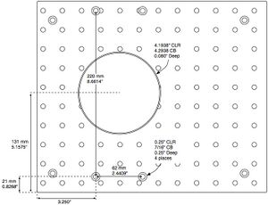
With that said, we wanted the stage to be customizable and have the ability to attach other optics to it. This lead us to using an aluminum breadboard modified so that it would fit on the microscope. One very nice thing about this plate is that it allows the microscope to retain all its microscopy functionality and it is unobtrusive.
So from my understanding with optical tweezers you want to have the ability to "steer" your beam. There are 3 possibilities to do this and they include: moving the lens of a telescope, using an optical deflector, or using a piezo stage. Using a telescope has the possibility of introducing aberrations and an optical deflector are expensive and they mess with beam quality. So, we opted for using a piezo stage with sub nanometer resolution from Mad City Labs. Going with this option means that we had to design a platform for the PZ to sit on. Again, we used pre-made parts to do this. Originally a design was made to create our own parts but it ended up not fitting properly on the microscope thus wasting lots of man hours machining. This is why I am all about not machining except as a the last resort. You will be surprised to realize that most everything you need to build can be purchase from lots of different companies.
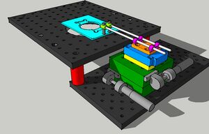
At any rate, the new design ended up using the original design idea which uses a ledge to hold the PZ off of the microscope plate. Below you can see my 3D model of our Sample Translator Plate.
All items save one shown can be purchase from different companies so there is minimal machining involved. The only part that needed to be fully made was the orange one. The yellow one is a modified baseplate from Newport that we only needed to tap 4 holes in. I can't find my diagram for the part I had to completely machine, but once I do find it, I'll post it.
Parts List
| Component | Model Number | Cost | # Needed | CAD Drawing | Sketchup |
| 10" x 12" breadboard | MB1012 | $164.60 | 1 | Yes | Yes |
| 6" x 12" breadboard | MB612 | $124.00 | 1 | Yes | Yes |
| ø1" x 2" posts | RS2 | $20.00 | 2 | Yes | Yes |
| ø1" x 0.12" spacer | RS01 | $6.80 | 2 | Yes | Yes |
| 1" translation stage | 426 | $428.40 | 2 | Yes | Yes |
| I used only the top baseplate and tapped 4 holes in it | MB-3 | $72.42 | 1 | Yes | [Not yet] |
| PZ stage | Nano-OP30 | A lot! | 1 | Yes | Yes |
| [Orange part] | Awesome | Nothing but time | 1 | [Not yet] | [Not yet] |
| Diving board rod holder | SMB1 | $15.50 | 2 | Yes | Yes |
| ø3 mm x 6" rods | SR6 | $8.70 | 2 | Yes | [No] |
| ø6 mm x 1" rods | ER1 | $5.18 | 2 | Yes | [No] |
| Right angle rod holder | ER90B | $12.40 | 2 | Yes | Yes |
Condenser & Detector stage New
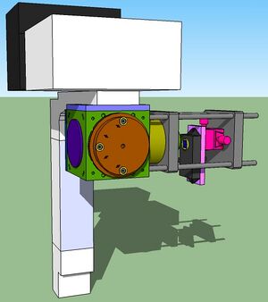
Our microscope is an IX71 from Olympus. We have the standard illumination arm IX2-ILL100 that has M3 screws around the field stop that allows us to mount optics to. We have decided to go with a cage/cube setup that allows us to mount our QPD directly to the illumination arm. See below figure.
SJK 01:21, 24 February 2009 (EST)

I love these sketchups more than I do optical breadboards -- you know that means a lot.
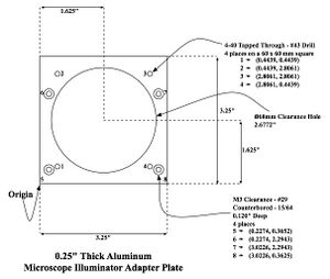
A parts list for the setup will hopefully show up below. The nice thing about this setup is that the microscope is not modified in any way shape or form. We can mount one of Thorlabs' 60 mm cubes to the illumination arm by use of an adapter plate. We have not built the adapter plate just yet, but a design for it is below.
Using the cube setup allows us to mount a dichroic to steer our laser onto our QPD. The QPD is then mounted on postitioners that are mounted on a cage plate.
Detector Stage Parts List
| Component | Model | # Needed | Cost | CAD Drawing | Sketchup |
| Adapter | N/A | 1 | Machining time | See above diagram | [Not yet] |
| Ø6 mm x 0.5" Long Cage Assembly Rod | ER05 | 4 | $4.94 | Yes | [Not yet] |
| 60 mm Cage System Cube with Ø6 mm Clearance Holes | LC6W | 1 | $124.00 | Yes | Yes |
| Blank Cover Plate with Rubber O-Ring for LC6W | LB1C | 1 | $30.20 | Yes | Yes |
| SM2 Series End Cap | SM2CP2 | 1 | $26.50 | Yes | Yes |
| Rotatable Kinematic Cage Cube Platform for LC6W | LB4C | 1 | $126.00 | Yes | Yes |
| Ø2" Cage Cube Optic Mount For LB3C | LB5C | 1 | $54.60 | Yes | [Not Yet] |
| Ø2" x 1" Long SM2 Lens Tube | SM2L10 | 1 | $29.60 | Yes | Yes |
| 60 mm Threaded Cage Plate | LCP01 | 1 | $31.30 | Yes | Yes |
| Adapter with External SM2 Threads and Internal SM1 Threads | SM2A6 | 1 | $23.50 | Yes | Yes |
| Ø1" x 0.5" Long SM1 Lens Tube | SM1L05 | 1 | $12.59 | Yes | Yes |
| QPD | SiQu50-M | 1 | ?? | Yes | [Not Yet] |
| 0.5" XY Dovetail Translation Stage | DT12XY | 1 | $130.00 | Yes | [Not Yet] |
| 60 mm Blank Cage Plate | LCP03 | 1 | $32.60 | Yes | Yes |
| Ø6 mm x 6.0" Long Cage Assembly Rod | ER6 | 4 | $8.27 | Yes | [Not Yet] |
Condenser quandaries
The above setup for our QPD seems to be right along the lines that we want it to be. Unfortunately, we are in a debate as to how to mount our condenser. As can be seen, our entire goal is to machine as little as possible and make our setup highly reproducible and easily accessible to every lab on the planet. But, we are at a loss for the condenser setup right now.
Our loss is mainly due to Olympus and their shady business practices of keeping parts and part numbers from consumers. I guess this helps them as a company because they can over charge and keep their consumers in the dark, but from my stand point, this makes them greasy and an undesirable company to use.
On the standard illumination arm IX2-ILL100 (I had to search real hard to get that number...in fact, here is a list of their part numbers for the IX71) there is a spot to hold condensers. One nice thing about this condenser holder is that it is on a rack and pinion system that allows us to move the condenser up and down easily. The disadvantages of this system is that Olympus does not make a rack and pinion system for high NA condensers and you have to deal with their lead screws to center your condenser.
The worst part about not selling high NA condensers is that they do sell a sort of fix that is astronomically expensive.
On the condenser holder is a dovetail mount that mates Olympus condensers. Olympus doesn't sell these by themselves. It would be nice to have the dovetail so that we could mount it on a lens tube system and then to a condenser of our choice, but that would be too easy. Instead, if we want to use Olympus' illumination arm with their condenser holder we will have to buy a condenser with their proprietary dovetail system and rip it apart so that we can mount it they way we want. Irritating.
Another solution is to just forget about Olympus and their dicey business practices and make our own condenser holder. To do this, we will need:
- x and y centering of the condenser
- z positioning that is as easy as a rack and pinion.
- easily mountable to our cube system
These are high orders and may proof to difficult to accomplish so we may have to just buy an Olympus condenser so that we can rip it apart.
- Steve Koch 01:23, 24 February 2009 (EST):Ripping apart the Olympus condenser is fine. I also like the idea of getting John to machine it--if you think designing that wouldn't be so bad, it probably makes sense in the long run, since we'll probably need more of these dovetails in the coming years.


