The Benefits of Small Length Scales in Microscale Systems - Duy Nguyen

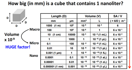
Microscale systems operate under a unique physical environment that contribute to their portability and low cost, making them ideal for point-of-care applications. These characteristics can be attributed to the benefits of the micron length scale, where extensive properties, such as mass, play a less significant role. Microfluidic systems often operate under the laminar flow regime, which is characterized by streamlined flow with little mixing. Surface effects, such as capillary action, also become increasingly significant in driving flow. In addition, heat transfer in microfluidic systems is primarily dictated by conduction. These properties can be attributed to the scaling nature of the surface area to volume ratio (Figure 1).
Laminar Flow
Flow in microfluidic systems experience minimal mixing due to the lack of turbulence when working on the micro-scale. The Reynolds number, a dimensionless number that describes the flow regime of the system by relating inertial and viscous forces, is given by:
- [math]\displaystyle{ \mathrm{Re} = \frac{Inertial}{Viscous} = \frac{\rho v L}{\mu} }[/math]
where:
- [math]\displaystyle{ \rho }[/math] is the density of the fluid (kg/m^3)
- v is the velocity of the fluid (m/s)
- L is the characteristic length of the channel, which varies for circular pipes, square ducts, and other geometric channels (m)
- [math]\displaystyle{ \mu }[/math] is the dynamic viscosity of the fluid (Pa*s)
Given that the Reynolds number is directly proportional to the characteristic length (L) of the channel, flow in microscale channels often falls under the laminar regime as the Reynolds number does not come close to approaching the transition point for turbulent flow, which occurs at around 2300. In addition, the effects of inertia become minimal as inertia is dependent on mass, which becomes insignificant on the microscale.1 The significance of viscous effects over the inertial effects of the flow produce very little mixing. Under two-dimensional laminar flow, neighboring streamlines form a distinct boundary where diffusion occurs. This characteristic property of microfluidic channels allows for controlled diffusion rates that can be tailored to specific chemical reactions and other applications. At the same time, the slow nature of passive diffusion, depending on the diffusion coefficient, calls for active mixing methods that require either physical or chemical means.
Capillary Action
Flow in microscale systems is also heavily influenced by capillary action. Fluids within a narrow channel experience adhesion forces from the wall that pull the fluid along the channel. At the same time, cohesive forces between the liquid and itself impede movement of the fluid along the channel. The resultant action, between adhesion with the walls and cohesion with the molecules within the fluid itself, produces the capillary action that drives flow within the channel.1,2,3 Quantitatively, the capillary effect is described by the capillary number:
Capillary Number [math]\displaystyle{ = \frac{Viscous Forces}{Surface Tension} = \frac{\mu v }{\gamma} }[/math]
where:
- [math]\displaystyle{ \mu }[/math] is the dynamic viscosity of the fluid (Pa*s)
- v is the velocity of the fluid (m/s)
- [math]\displaystyle{ \gamma }[/math] is the surface tension of the fluid (N/m)
Low capillary numbers describe low mobility flow within the capillary channel, as surface tension forces dominate and cause the fluid to round up into itself. On the microscale, the effects from capillary action become increasingly dominant. The driving force for capillary action (adhesion between the walls and fluid) is a result of the contact area between the channel walls and fluid. At smaller length scales, the surface area to volume ratio increases drastically, as the surface area only decreases by the square of the characteristic length while the volume decreases by its cube.2 In summary, microscale systems have a relatively large capillary number, as the large surface area to volume ratio supplements adhesion of the fluid to the wall (larger surface area = more contact area for adhesion) while decreasing the viscous effects (smaller volume = less molecules in the fluid for cohesion)
Heat Transfer

Heat transfer refers to the movement of thermal energy between two objects at different temperatures. The movement of thermal energy is primarily driven by conduction, convection, and radiation. Conduction, which is the direct exchange of thermal energy, occurs at the boundary between two objects and is distinguished by the presence of contact between the two objects. Heat energy flows from the object of higher temperature to that of lower temperature until equilibrium is attained. Convection, on the other hand, involves the transfer of heat energy through the movement of fluids and gases. Unlike either conduction or convection, radiation is the transfer of energy via electromagnet waves that are emitted by the object.
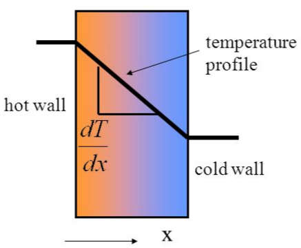
Heat transfer involves some combination of conduction, convection, and radiation. In microscale systems, however, heat transfer is primarily driven by conduction.4 While the nature of conduction can become complex due geometrical and surface roughness differences between two objects, a simplified approximation can be made between in order to accurately describe the heat transfer process at the microscale. In microfluidic systems, two adjacent streams form a distinct boundary. Because the Reynolds number is extremely low, little to no mixing occurs between these two streams. In the scenario where the two fluids move alongside each other with an equal velocity, the two fluid streams form a boundary equivalent to that of two parallel walls (Figure 2). In such a scenario, the heat transfer between the two streams can be described by Fourier's Law (Figure 3).

Applications
While they serve an increasingly wide array of functions, from chemical assays to blood filtration, microfluidic chips all exploit a physical phenomenon that occurs due to the nature of the microscale
Blood Plasma Separation
The point-of-care nature of microfluidic chips make them ideal for hemodynamic assays. Conventionally, blood analysis is performed in a lab where whole blood is separated via centrifugation in order to isolate plasma from whole blood. Blood plasma contains a number of molecular constituents, such as potassium, that can be used as a preliminary diagnosis for downstream healthcare treatments. Conventional blood analysis, however, requires specialized equipment and large blood draws that can impact the patient.
Microfluidic platforms are ideal for hemodyanmic assays in that they require a very small sample volume and take advantage of the natural phenomenon that occurs at the microscale for separations. Capillary-driven microfluidic chips have been shown to separate 2.0 μl of plasma from <10 μl of whole blood in 15 min with a purification efficiency of 99.9%.5. The device is entirely driven by capillary flow and eliminates the need for external equipment (Figure 4). The device demonstrates the capacity of a microfluidic chip to separate whole blood from plasma, which is the first major step in providing point-of-care diagnostics using microfluidic platforms.

Experimental Control

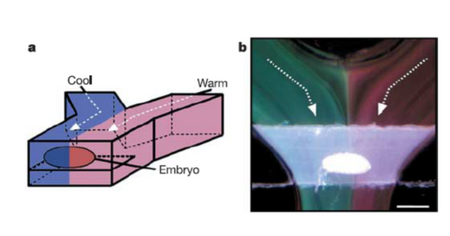
The controlled nature of flow within microfluidic systems serves as a valuable tool for a number of experimental studies. Due to the nature of microscale flow, it is possible to establish large temperature gradients using two adjacent flow streams. Because of the laminar flow profile of microscale systems, there is little mixing between fluids in straight/parallel channels. By introducing a hot stream and a cold stream, a large temperature jump can be established, as the main source of heat transfer between the two flow streams (conduction) is dependent only on the conductivity coefficient. This has been utilized to study embryonic development in fruit flies, where an embryo was placed in the center of two fluid streams (hot and cold).6 The large temperature gradient did drastically alter embryonic patterning and development, when measured by percent elongation of the embryos anterior and posterior.6
References
1. Squires, T., & Quake, S. (2005). Microfluidics: Fluid physics at the nanoliter scale. Reviews of Modern Physics. https://doi.org/10.1103/RevModPhys.77.977
2. Novotný, J., & Foret, F. (2017). Fluid manipulation on the micro-scale: Basics of fluid behavior in microfluidics. Journal of Separation Science. https://doi.org/10.1002/jssc.201600905
3. https://www.khanacademy.org/science/biology/water-acids-and-bases/cohesion-and-adhesion/v/capillary-action-and-why-we-see-a-meniscus.
4. Ozsun O, Alaca BE, Yalcinkaya AD, Yilmaz M, Zervas M, Leblebici Y. On heat transfer at microscale with implications for microactuator design. Journal of Micromechanics and Microengineering. 2009;19(4):045020. doi:10.1088/0960-1317/19/4/045020.
5. Maria, M., Rakesh, P., Chandra, T., & Sen, A. (2017). Capillary flow-driven microfluidic device with wettability gradient and sedimentation effects for blood plasma separation. Scientific Reports. https://doi.org/10.1038/srep43457
6. Lucchetta EM, Lee JH, Fu LA, Patel NH, Ismagilov RF. Dynamics of Drosophila embryonic patterning network perturbed in space and time using microfluidics. Nature. 2005;434(7037):1134-1138. doi:10.1038/nature03509.
