Surface Wetting - Chris Ortins
Surface Wetting Applications
Wetting Morphologies at MIcrostructured Surfaces
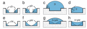
Being able to efficiently work with small amount of liquids is an integral skill in industries including biomedicine and molecular biology. This study uses open microfluidic systems which have free liquid/vapor interfaces because these systems have the advantage of being more accessible and easier to clean. The focus of the research is the filaments that develop in the grooves and their geometry that can remain constant throughout the length of the groove. The certain morphologies were were obtained by matching surface topography and wettability by using two parameters: the aspect ratio (X) of the groove geometry and the contact angle (θ). The liquid/ vapor interfaces that dictate the shape of the liquid re characterized by the mean curvature, M, and contact angle. The mean curvature is found using the interfacial tension, Σ, and Laplace Pressure, PLa, using the Laplace equation: 2MΣ = PLa1

PDMS Microfluidic Channels
Surface wetting can be use to create microfluidic channels of desired quality. An experiment was done to create cylindrical PDMS channels with tangential chord angles (TCAs) close to 90 degrees by exploiting support materials and varying their surface contact angle (SCA). The TCA is final angle of the solid channel while the SCA amounts to the angle θ involved in the Young's relation for a liquid in air4:

- [math]\displaystyle{ cos(\theta) = \frac{(\gamma_s − \gamma_{sl})}{\gamma_{lv}} }[/math]

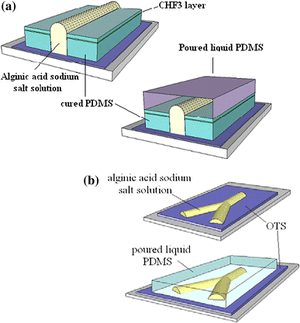
γs denotes the surface tension of the solid surface, γsl is the solid-liquid surface tension, and γlv is the liquid-vapor surface tension. The creation of these channels was based on optimizing the wetting parameters. The optimization created hydrophilic and hydrophobic steps to create the channel pattern definition with alginic acid sodium salt aqueous solution. The first method uses PDMS coated with CHF3 on a silicon wafer. The PDMS is cut in strips wit the middle taken out and the alginic acid sodium salt aqueous solution is poured in the middle. Since the hydrophilic aqueous solution does not spread to the hydrophobic strips, the channel definition is formed and PDMS is then poured over the top to create the channel. The second method uses octadecyltrichlorosilane (OTS) coated surface that is degraded with UV and O3. A shadowmask is used to cover the OTS surface except for the places to be degraded to create a hydrophobic/hydrophilic contrast, which allows for more complex channels. After the OTS surface is degraded the aqueous salt solution is poured and created channel definition on the degraded OTS. Results showed that the first method was more effective withTCAs up 70 degrees, while the second method sees its best channels with TCAs of only 55 degrees4.
Thermal-Responsive Anisotropic Wetting Microstructures for Manipulation of Fluids in Microfluidics
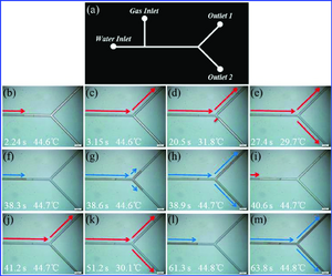
PNIPAAm-modified Si stripes on silicon slides were made as substrates for manipulating the flow motion of fluid on a chip. PNIPAAm is a thermally responsive polymer which can be used to dictate the flow of a fluid. The polymer has a lower critical solution temperature and when the temperature of the system goes above and below this temperature the wettability of the liquid switches between strong and weak anisotropy. The flow in the microchannels was both anisotropic and isotropic at different times with different temperatures. The three parameters that influenced the thermal-responsive flow motion are applied pressure, the thickness of the polymer, and the dimensions of the microchannels. This study concluded that this system could be used as a thermal-responsive microvalve after applied pressure tests were conducted, the system temperature was able to be tuned, and the assistant gas was added. This technology could be used in many practical biomedical practices including immunodetection and protein analysis2.

Effect of wetting on capillary pumping in microchannels
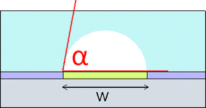
Being able to control flow in a microfluidic system is very important and one way liquid moves in these small spaces is the difference in Laplace pressure. If two drops with the same contact angle in a channel the smaller drop has a greater Laplace pressure since it is defined by the liquid-vapor surface tension divided by the radius of the drops curvature. However, wetting properties can be manipulated using two parameters, radius of contact line (Rw) and contact radius (θ), if the drops are spherical caps and the pressure can be calculated using this equation3:
- [math]\displaystyle{ \frac{2\gamma}{R_w} sin(\theta) }[/math]
This equation allows for the potential of larger drops to flow towards small drops since the Laplace pressure is so dependent on the contact angle. If the contact angle of the large drop is close to 90° and a smaller drop has a smaller contact angle, then the Laplace pressure of the large drop would be larger and flow would be towards the smaller drop. Results were found by ana;yzing movies using a CCD camara at 125 frames/s. It was found that backflow occurred when there was a large difference in the surfaces under the drops and the pressure of the larger drop was larger than the pressure of the smaller drop. Since smaller initial contact angles of the smaller drops resulted in more backflow it was concluded that wetting properties can be used for active pumping3.
Principle of electrowetting based lenses and applications to imaging
Optical parts are smaller than ever and when they are need in the 1-10mm range, manipulating liquid droplets may be an effective method of developing the lenses. The biggest obstacle facing these types of lenses is stabilizing the optical axis. Electrowetting is used for the liquid-liquid interface by changing the relative wettabilities of the liquids by applying a voltage. The densities of the liquids must be exact so any orientation of axis is possible and can be controlled by slightly changing liquid composition. The most important aspect of stabilizing the optical axis is centering the liquid drop, which was done using a dielectric thickness gradient as well as geometry. An equation for the contact angle of the oil drop on the planar surface, including the the insular film thickness (e) and dielectric constant is: cos(θ)=cos(θ0)- 1/2 εε0/(eγ)(V2). The results showed that the centering methods worked very efficiently. Stabilizing the optical axis can be done by centering the liquid-liquid interface and this type of lens could be used as an optical component of a more complex system5.
References
1. Seemann, R.; Brinkmann, M.; Kramer, E.; Lange, F.; Lipowsky, R. Wetting morphologies at microstructured surfaces. PNAS. February 8, 2005. https://doi.org/10.1073/pnas.0407721102
2. Yu, N.; Wang, S.; Liu, Y.; Xue, P.; Ge, P.; Nan, J.; Ye, S.; Liu, W.; Zhang, J.; Yang, B. Thermal-Responsive Anisotropic Wetting Microstructures for Manipulation of Fluids in Microfluidics. Langmuir 2017 33 (2), 494-502. https://doi.org/10.1021/acs.langmuir.6b03896
3. Javadi, A.; Habibi, M.; Taheri, F.S.; Moulinet, S.; Bonn, D. Effect of wetting on capillary pumping in microchannels. Scientific Reports volume 3, Article number: 1412 (2013). https//doi.org/10.1038/srep01412
4. De Ville, M., Coquet, P., Brunet, P., & Boukherroub, R. (n.d). Simple and low-cost fabrication of PDMS microfluidic round channels by surface-wetting parameters optimization. Microfluidics And Nanofluidics, 12(6), 953-961. https://doi.org/10.1007/s10404-011-0929-8
5. Berge, B. Liquid lens technology: principle of electrowetting based lenses and applications to imaging. Micro Electro Mechanical Systems, 2005. https//doi.org/10.1109/MEMSYS.2005.1453908
