Stereolithography
Stereolithography is a 3D printing technique used to make scaffolds for tissue engineering. Structures are created by using a beam of ultraviolet light to solidify specific areas of liquid polymer in a vat.
Background/History
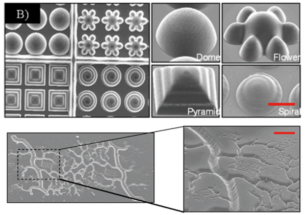
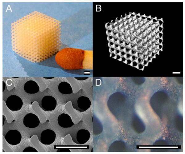
Stereolithography is a solid freeform technique first used by engineers to rapidly create prototypes. Hideo Kodama was the first to develop 3D printed structures using photopolymerizable materials in the 1970s. In 1986, Chuck Hull created the term stereolithography with the foundation of 3D Systems Inc to model car parts[3]. Traditional prototyping involves time consuming molding and casting, but stereolithography is faster and easily reproducible. The high fabrication accuracy allows for the production of structures on the 20 um scale compared to 50-200 um.[3] However, this higher resolution comes with a smaller maximum size of parts. Figure 1 shows the complexity of structures that can be created using stereolithography. [1][2]
As the technology develops, more materials are becoming available for use, fabrication costs are decreasing, and the properties of the manufactured parts are becoming better. Stereolithography was first used for biomedical applications as a biomaterial for implants, as its process means that patient-specific models can be made from medical scans. Stereolithography was initially limited by the low number of polymers that could be used, but as more work has been done, researchers have developed ways to functionalize different polymers. In 2000, the first biodegradable structures were made via stereolithography.[3] Due to the high resolution and precise geometries that can be created, stereolithography has been adapted to make scaffolds for tissue engineering.
Process
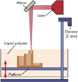
The process begins with a computer model, often a CAD image, that is virtually sliced into layers typically 25 - 100 um thick.[3] The file is then uploaded to a stereolithography apparatus, where a computer controlled beam of light crosslinks a thin layer of liquid polymer in a certain pattern (Figure 2). Growth in the third dimension is controlled by moving a platform with the structure away from the surface after light has been shined and repeating. To adhere layers to one another, the depth of curing is set slightly larger than the platform step height. The excess resin is then either drained or washed off, which leads to a green or as-fabricated structure, where the conversion of reactive groups is not fully complete.[5] Generally structures are post-cured with stroboscopic UV light to improve mechanical strength.
There are several different approaches to stereolithography. Figure 2 shows the bottom-up approach, which uses a controlled laser beam to mark patterns in the xy plane. The platform is then lowered and the surface gets recovered with liquid resin using a blade. The thickness of the layers depends on the power of the laser.[5]
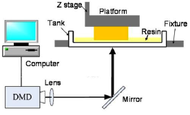
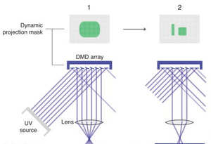
In the top-down, projection-based approach seen in Figure 3, the platform is lowered to be slightly above the bottom of the vat. Using a Digital Micromirror Device (DMD) (Figure 4), an array of millions of micromirrors that can be rotated independently to an on-off state, a 2D pixel pattern is projected through the transparent bottom of the vat onto the platform.[6] The thickness of the layers depends on the length of projection time. The vat is then rocked to peel away the bottom layer, and resin rushes in to fill the gap as the platform is raised. [3]
The top-down, projection-based approach holds several advantages over the bottom-up approach:
- The structure can be much larger than the depth of the vat[5]
- Recoating of the structure is not required
- The illuminated surface is always smooth
- Only enough resin to fill the bottom of the vat is required, conserving expensive polymer. This helps to decreases waste of the polymer by limiting oxygen inhibition via exposure to atmosphere [3]
- Build time is reduced and there are no concerns over the xy size, as entire layers are solidified at once
- Multiple structures can be built simultaneously[7]
Materials
Stereolithography requires fairly low molecular weight, multifunctional monomers that can lead to highly crosslinked networks when crosslinked with polymerization. Originally, the polymers used were glassy, rigid, and brittle, however recent advancements have led to the functionalization of many more materials.
Polymers such as poly(ethylene glycol) (PEG), poly(ε‐caprolactone) (PCL), poly(trimethylene carbonate) (PTMC), poly(propylene fumarate) (PPF), and poly(D,L‐lactide) (PDLLA) have been used and functionalized with photoreactive groups like methacrylate (MA) for use in tissue engineering. [3][7][8] [9] Materials such as PEGDA hydrogels have been used with cells with some success, but they are not degradable, while the low elasticity and low glass transition temperatures of TMC, PCL, and PPF are not ideal for use in scaffolds.[7] Some materials like DLLA and PPF need to be mixed with a diluent to reduce the high viscosity of the polymers, as the maximum viscosity that can be used with stereolithography is 5 Pa-s.[3] If the diluent is nonreactive, the structure will shrink when the diluent is extracted after completion of the structure.
These materials have been shown to support cell adhesion and growth, hoverer cell-structure interactions may not be very strong with synthetic polymers. To overcome this hurdle, bioactive compounds like hydroxyapatite (HA) or specific protein‐binding molecules can be mixed into the resin to promote adhesion. Other work has been done to modify natural based polymers with beneficial cell binding sequences, such as gelatin, chitosan, and oligopeptides.[8]
To undergo photopolymerization, the resin must be mixed with a photoinitiator to start the addition polymerization. However, many initiators are toxic to cells. The most commonly used initiator is Irgacure 2959 (IRG), the least cytotoxic of known initiators. Concentrations of initiator typically range between 0.5 to 2 w/v %. [10]
Applications
The primary application in tissue engineering is to create complex and well-defined scaffolds. Stereolithography allows scaffolds to be optimized for pore structure and connectivity, geometry, mechanical properties, cell-seeding efficiency, and transport of nutrients and metabolites[7]. The pore network has been shown to affect tissue growth.
Scaffolds for Bone Tissue Engineering
Poly(D,L-lactic acid) Scaffolds
PDLLA has been used clinically in resorbable bone devices. It has an elastic modulus around 3 GPa, similar to that of bone (3-30 GPa), and can be functionalized with several reactive groups[7].
Using PDLLA modified with MA and an unreactive ethyl lactate diluent, Mechels et al. were able to create scaffolds for bone tissue engineering (Figure 5). Due to the diluent, there was a 10% shrinkage in all directions once it was removed. Using projection-based stereolithography, 30 scaffolds were simultaneously made with a building time of 5 hours. [7] Structures can be made up to 42x33x200 mm^3 in size, using a layer thickness of 25 µm and light pixels 32x32 µm^2 that limit the smallest features that can be built. To reduce the overcure to within the layer thickness, a small amount of orange dye was added to reduce the overcure between layers from 29 to 7 µm. The created scaffolds had a porosity of 75% with pore sizes around 200 µm. Flexural moduli ranged between 2.5-3.5 GPa and were tested using three point bending tests.
The gyroid architecture shown in Figure 5c allows for better permeance of water through the scaffold than other designs. A cell suspension of mouse pre-osteoblasts was seeded onto the scaffold, and proliferated and adhered well to the structures. In comparison, scaffolds made by salt-leaching or freeze-drying have highly tortuous and poorly connected pore networks that hindered the penetration of cell suspensions[7].
Other studies have shown that changing molecular weight of the PDLLA used did not significantly affect osteoblast proliferation and spreading.[3] Work has also been done using copolymers of PCL to create high-resolution scaffolds with cubic, diamond, and gyroid geometries. In another study, Melchels was also able to create gyroid scaffolds with pore size and porosity gradients.[11]
Poly(Propylene Fumarate) Scaffolds
PPF has nontoxic degradation products that are intermediates in glucose metabolism, and has mechanical properties similar to trabecular bone that make it a good candidate for bone tissue scaffolds. Synthesis of scaffolds was done by diluting with diethylfumarate (DEF) in ratios 60:40 and 75:25 PPF/DEF with BAPO initiator concentrations ranging from 0.5 to 2%. The produced scaffolds had well-defined pore sizes, pore geometries, and porosities.[9] Lee et al. evaluated the effect of internal geometry on differentiation and growth and found that the more complex staggered network showed improved growth in comparison to simpler lattice structures. Growth and mechanical properties of these constructs were superior to scaffolds with the same porosity made by the more standard particulate leaching or gas foaming.[12] Kim et al. also showed better results in comparison to leached scaffolds, with those made via stereolithography being more permeable to cells. Osteoblasts also expressed higher amounts of growth factors.[13] Other materials have been added to enhance the initial adhesion and growth, such as Arg–Gly–Asp (RGD) peptides and hydroxyapatite coatings or nanoparticles. In one study, PLGA microspheres loaded with Bone Morphogenic Protein 2 (BMP-2) were incorporated into the scaffolds, and the gradual release helped bone formation in rat cranial bones.[14] 
Multi-Cellular and Muti-Material Constructs
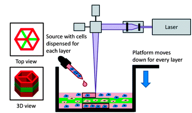
Stereolithography can also be used to encapsulation a variety of cell types. Human dermal fibroblasts, mouse fibroblasts, mesenchymal stem cells, embryonic liver cells, and chondrocytes have already been used in stereolithography-made structures. [8] In one study, PEGDA hydrogels were used to encapsulate fibroblasts. [15] Using 20% PEGDA to make hydrogel scaffolds, the molecular weight of the polymer was varied from 3400 to 5000 Da resulting in elastic moduli ranging from 5-500 kPa [15]. The swelling ratio increased with molecular weight. By printing differently dyed layers, Chan et al. were able to show that it is possible to print different layers containing different cell types with minimal mixing.
It was also noted that cells spread only when RGDS peptide binding sequences were added, which was why the viability after 2 weeks was poor. It was suggested that PEG could be modified with short peptides in its backbone for enzymatic cleavage by the encapsulated cells or made into a co-polymer with poly(lactic acid) [15]. In a similar study, cell migration was controlled by patterning specific layers using (RGDSK) peptides. Cells migrated from clusters to those patterned regions[16].
Stereolithography and PEGDA scaffolds can be used to model in vitro responses more similarly to in vivo conditions, especially in regards to modeling cancer cell migration in three dimensions. By varying the concentration of PEGDA from 19 to 95%, it is possible to create scaffolds with greatly varied mechanical properties (0.9 to 5.5 MPa). Soman et al. found that cancer cells actually migrated differently in 3D compared to 2D structures. [17]
Scaffold-Reinforced Hydrogels
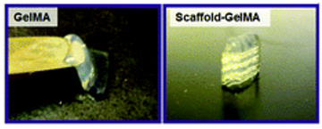
A natural-based hydrogel, gelatin methacrylate (GelMA), has been used at concentrations of 15% in stereolithography to create log pile and hexagonal scaffolds that supported the spreading and proliferation of immortalized human umbilical vein endothelial cells (HUVECs) that were seeded on the structures.[18] Although GelMA has been shown to have many properties that mimic the native extracellular matrix, it lacks lack rigidity and mechanical strength, causing the structures to distort over time. To better support hydrogels, Cha et al. developed a composite scaffold.[10] Very weak 5% GelMA hydrogels with elastic moduli of 0.3 kPa were formed around stereolithography-printed PEGDA scaffolds. While unsupported hydrogels swelled and disintegrated after 7 days, the scaffold-supported hydrogel maintained its structural integrity. Encapsulated fibroblasts had similar viability and spreading on both GelMA and scaffold-GelMA constructs. [10]
Indirect Stereolithography
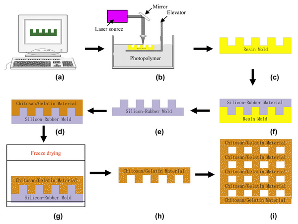
Stereolithography can also be combined with other techniques to create more complex scaffolds. In indirect stereolithography, the SLA is used to create a sacrificial mold from which the scaffold is created. Potential applications include creating scaffolds from very soft or viscous materials, as in gel casting or with bioceramics like hydroxyapatite.[8]
Chitosan/Gelatin Scaffolds for Liver Tissue Engineering
Jiankang et al. created scaffolds for liver tissue by combining stereolithography, microfabrication, and freeze-drying. Liver tissue scaffolds need an interconnected pore network to allow for the transport of nutrients, oxygen, and waste. Since liver tissue is highly vascularized, scaffolds should also have predefined vascular channels to promote angiogenesis.
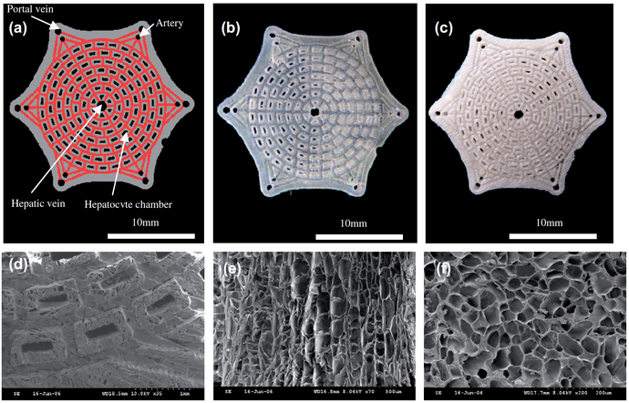
Jiankang et al. made prototype resin scaffolds using stereolithography, then made negative silicon-rubber molds using microreplication. A chitosan/gelatin mixture was placed in the mold and freeze-dried to create a finished scaffold unit (Figure 8). Freeze-drying creates highly porous (90-95% porosity) structures, but the pores are randomized and poorly connected. Stereolithography is a good technique for creating microstructures, but liver scaffolds made from biodegradable polylactic acid (PLA) or polylactic-co-glycolic acid (PLGA) may lack adhesion. Chitosan and gelatin have good biocompatibility, biodegradability, low toxicity, and low cost, and hepatocytes have been shown to adhere and proliferate on porous chitosan scaffolds. The use of stereolithography allowed for the creation of structures with complex, defined microstructures, as shown in Figure 9. The portal vein, artery, hepatocyte chambers, hepatic vein, as well as vascular branching angle were designed to mimic the natural architecture of the liver. The blood could flow in via the six portal veins and arteries, mix at the interconnected channels, and then flow out from the hepatic vein.[19] Hepatocytes can be seeded into the hepatocyte chambers, allowing room for aggregation. The created scaffolds had a 90-98% porosity with pore sizes ranging from 17 um to 115 um. Hepatocytes seeded onto the scaffolds attached and proliferated more than on scaffolds made only with freeze-drying. After 3 days, multicellular spheroidal aggregates started to form on the defined scaffolds. Future improvements to the scaffold would combine multiple cells types to further encourage growth.[19]
Issues with Stereolithography
Although advanced scaffolds can be created using stereolithography, there are still some limitations. Depending on the stereolithography apparatus, it may be difficult to create micron-sized features. This is due to restrictions on the layer thickness and overcuring, which can cause resin to partially polymerize in bottom layers.[3] The size of the light pixels also limits microstructure creation in the xy direction. There are also a limited number of materials suitable for functionalization, restricted by viscosity, stability, and transparency. When dealing with encapsulated cells, there are also some potentially cytotoxic effects due to the initiator and irradiation with UV light.[3] However, it is generally agreed that in small doses the cytotoxic effects are minimized.[8] While indirect stereolithography can overcome some of these limitations, these methods can be expensive and time-consuming since more materials are used.
By Brian Cain.
References
-
Hribar, K.; Soman, P.; Warner, J.; Chung, P.; Chen, S. Light-Assisted Direct-Write Of 3D Functional Biomaterials. Lab Chip 2014, 14, 268-275.
-
Zhang, A.; Qu, X.; Soman, P.; Hribar, K.; Lee, J.; Chen, S.; He, S. Rapid Fabrication Of Complex 3D Extracellular Microenvironments By Dynamic Optical Projection Stereolithography. Adv. Mater. 2012, 24, 4266-4270.
-
Melchels, F.; Feijen, J.; Grijpma, D. (2010) A review on stereolithography and its applications in biomedical engineering. Biomaterials, 31(24). pp. 6121‐6130.
-
(18) Kerns, J. 3D Printing Tips and Tech: Get to Know Those Acronyms http://machinedesign.com/manufacturing-equipment/3d-printing-tips-and-tech-get-know-those-acronyms (accessed Mar 2, 2016).
-
Pan, Y.; Zhou, C.; Chen, Y. A Fast Mask Projection Stereolithography Process For Fabricating Digital Models In Minutes. Journal of Manufacturing Science and Engineering 2012, 134, 051011.
-
Soman, P.; Chung, P.; Zhang, A.; Chen, S. Digital Microfabrication Of User-Defined 3D Microstructures In Cell-Laden Hydrogels. Biotechnol. Bioeng. 2013, 110, 3038-3047.
-
Melchels, F.; Feijen, J.; Grijpma, D. A Poly(D,L-Lactide) Resin For The Preparation Of Tissue Engineering Scaffolds By Stereolithography. Biomaterials 2009, 30, 3801-3809.
-
Skoog, S.; Goering, P.; Narayan, R. Stereolithography In Tissue Engineering. J Mater Sci: Mater Med 2013, 25, 845-856.
-
Kim K, Yeatts A, Dean D, Fisher JP. Stereolithographic bone scaffold design parameters: osteogenic differentiation and signal expression. Tissue Eng Part B. 2010;16(5):523–39.
-
Cha, C.; Soman, P.; Zhu, W.; Nikkhah, M.; Camci-Unal, G.; Chen, S.; Khademhosseini, A. Structural Reinforcement Of Cell-Laden Hydrogels With Microfabricated Three Dimensional Scaffolds. Biomater. Sci. 2014, 2, 703-709.
-
Melchels FPW, Velders AH, Feijen J, GrijpmaDW. Photo-cross-linked poly(D, L-lactide)-based networks. Structural characterization by HR-MAS NMR spectroscopy and hydrolytic degradation behavior. Macromolecules. 2010;43:6579–8570.
-
Lee JW, Ahn G, Kim JY, Cho DW. Evaluating cell proliferation based on internal pore size and 3D scaffold architecture fabricated using solid freeform fabrication technology. J Mater Sci Mater Med. 2010;21:3191–205.
-
Kim K, Dean D, Wallace J, Breithaupt R, Mikos AG, Fisher JP. The influence of stereolithographic scaffold architecture and composition on osteogenic signal expression with rat bone marrow stromal cells. Biomaterials. 2011;32:3750–64.
-
Lee JW, Kang KS, Lee SH, Kim JY, Lee BK, Cho DW. Bone regeneration using a microstereolithography-produced customized poly(propylene fumarate)/diethyl fumarate photopolymer 3D scaffold incorporating BMP-2 loaded PLGA microspheres. Biomaterials. 2011;32:744–52.
-
Chan, V.; Zorlutuna, P.; Jeong, J.; Kong, H.; Bashir, R. Three-Dimensional Photopatterning Of Hydrogels Using Stereolithography For Long-Term Cell Encapsulation. Lab on a Chip 2010, 10, 2062.
-
Lee, S.; Moon, J.; West, J. Three-Dimensional Micropatterning Of Bioactive Hydrogels Via Two-Photon Laser Scanning Photolithography For Guided 3D Cell Migration. Biomaterials 2008, 29, 2962-2968.
-
Soman, P.; Kelber, J.; Lee, J.; Wright, T.; Vecchio, K.; Klemke, R.; Chen, S. Cancer Cell Migration Within 3D Layer-By-Layer Microfabricated Photocrosslinked PEG Scaffolds With Tunable Stiffness. Biomaterials 2012, 33, 7064-7070.
-
Gauvin, R.; Chen, Y.; Lee, J.; Soman, P.; Zorlutuna, P.; Nichol, J.; Bae, H.; Chen, S.; Khademhosseini, A. Microfabrication Of Complex Porous Tissue Engineering Scaffolds Using 3D Projection Stereolithography. Biomaterials 2012, 33, 3824-3834.
-
Jiankang, H.; Dichen, L.; Yaxiong, L.; Bo, Y.; Bingheng, L.; Qin, L. Fabrication And Characterization Of Chitosan/Gelatin Porous Scaffolds With Predefined Internal Microstructures. Polymer 2007, 48, 4578-4588.
