Spin Coating - Yizhuo Chen
Introduction to Spin Coating
Spin coating is a commonly used technique to create thin films of controlled thickness on a substrate. This method can easily and quickly create a very uniform film in a specific thickness range from only several nanometers to hundreds of microns. Spin coating is widely used in a variety of industrial and researching areas. Some industrial application of spin coating include electronics, nanotechnology and microfluidics.
Method


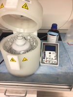
Spin coating is a commonly used procedure to uniformly make thin-layer films to flat the substrates. On the center of the substrate, certain amount of the coating material is placed on a flat substrate. The spin coater, also referred to as a ‘spinner’, then rotates the substrate to generate a centrifugal force and define the film. A typical spin coating procedure involves the following steps:
- (1) The substrate should be rotated at a low speed spinning in order to spread the coating material well-covered on the entire substrate or be placed without spinning at all until the coating material naturally well-covered on the entire substrate.
One alternative method is to only begin spinning after the material has covered the entire surface, if the material is a low viscous material.
- (2) The substrate should be rotated at a relatively high speed in order to spread the coating material by centrifugal force.
- (3) The spinner keeps rotating. At the same time, the excess coating material is flung off of the edges of the substrate. The thickness of the coating material on the membrane gets thinner and thinner until the film reaches to the expected thickness.
Film Thickness as a Function of Spin Speed
The coating layer thickness (h) depends on the time (t) spent on the rotation, fluid viscosity (μ), angular velocity of the turntable (ω) and fluid density (ρ). In order to understand this correlations, a fluid dynamic equation is required to solve the spin coating process. A model developed by Emslie et al.[2] is used for the process. This is not necessary for some applications, such as coating with photoresist or silicon oil, as their low viscosities allow them behave as Newtonian fluids. In industrial application, however, deriving an equation for the specific fluid viscosity is very necessary because the fluids used are commonly non-Newtonian, such as polymer solutions.
In the model of Emsile et al., the flow of the fluid is also assumed to be unidirectional in the radical direction. So only the radial component of the fluid velocity is not zero. What’s more, the fluid is assumed to be rotated together all the time with the substrate. So, the angular velocity of the fluid is:

So the equation of the fluid velocity in the cylindrical coordinate is:

Then the Navier-Stokes equations are:


Another assumption is that the height of the liquid on turnable is much smaller than the radius. So the rescaled coordinate could be introduced:

So the Equation 3 is transformed into the equation below:

After simplification, we obtain the equation:

The boundary conditions of the fluid velocity determined by:
- (1) The no-slip condition at the substrate surface,

- (2)The free surface condition between the fluid and the vaccuum

h(r,t) represents the height of the liquid and we got the following equation after integrating Equation 7 twice under the boundary conditions:

Equation 10 is used to describe the radial velocity correlated with the height h(r,t) of the film. The height of the film should be always much smaller than the radius. What's more, it may vary sometimes, which help us to neglect the correlation of the height on the position r and come up h(t) from the mass balance of radial direction.


So, after substituting Equation 12 into the mass balance equation, the following equations could be obtained:


Next step is to solve Equation 13, we get:

At h0 = h(t=0), we assume that:

So, Equation 15 comes up with the relation of the film thickness vs time and rotational velocity:

Spin Coating in Soft Lithography
PDMS

Polydimethylsiloxane (PDMS), in other terms dimethylpolysiloxane and dimethicone, is in the group of polymeric organosilicon compounds. Polymeric organosilicon compounds are always named as silicones in trademark.[3] PDMS is one of the most widespread organic silicon-based polymers well-known for its special rheological, chemical and mechanical properties. PDMS is an inert, bio-compatible, non-toxic, non-flammable and optically transparent polymer. PDMS is a polymerized siloxane, which is a type of silicone oil.[4] Due to it's impressive properties, PDMS has a wide range of applications. PDMS can be found in contact lenses, medical devices, shampoo to add shine to hair, the food industry as an antifoaming agent, and many lubricants. With regards to microfluidics, it is a prevalent in the field of soft lithography.
Film Thickness vs. Spin Speed
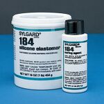
The final thickness of PDMS on the substrate (commonly a silicon wafer) mainly depends on both spin speed and spinning period. Other significant properties to get reproducible thickness of PDMS layer are type of PDMS, ratio between curing agent and elastomer, time spent in mixing of curing agent and elastomer, and temperature in environment[5][6][7]. PDMS is produced by combining the PDMS elastomer and curing agent (Sylgard 184, Dow Corning), which are mixed in a 10:1 weight to weight ratio then stirred for 2 minutes. After that, the PDMS is placed in a vacuum chamber for degassing for 10 to 13 minutes[5].

References
[1] Hellstrom, S.L. (2007), Published course work for physics 210, Stanford University, Autumn 2007. http://large.stanford.edu/courses/2007/ph210/hellstrom1/
[2] A. G. Emslie, F. T. Bonner, and L. G. Peck, “Flow of a Viscous Liquid on a Rotating Disk”, J. Appl. Phys. 29, 858-862 (1958) https://doi.org/10.1063/1.1723300
[3] Mata, A., Fleischman, A.J. & Roy, S. Biomed Microdevices (2005) 7: 281. https://doi.org/10.1007/s10544-005-6070-2
[4] "Linear Polydimethylsiloxanes" Joint Assessment of Commodity Chemicals, September 1994 (Report No. 26) ISSN 0773-6339-26.http://www.ecetoc.org/wp-content/uploads/2014/08/JACC-055-Linear-Polydimethylsiloxanes-CAS-No.-63148-62-9-Second-Edition.pdf
[5] Koschwanez, J. H., Carlson, R. H. & Meldrum, D. R. Thin PDMS Films Using Long Spin Times or Tert-Butyl Alcohol as a Solvent. PLoS ONE 4, e4572 (2009).https://doi.org/10.1371/journal.pone.0004572.
[6] F. K. Balagadde, L. You, C. L. Hansen, F. H. Arnold, S. R. Quake, Science 309:5731, 137‐140 (2005) https://doi.org/10.1063/1.4789751
[7] Zhang, W. Y., Ferguson, G. S. & Tatic-Lucic, S. Elastomer-supported cold welding for room temperature wafer-level bonding. in Micro Electro Mechanical Systems, 2004. 17th IEEE International Conference on. (MEMS) 741–744 (2004). https://ieeexplore.ieee.org/stamp/stamp.jsp?tp=&arnumber=1290691&tag=1
