Ring Mixers - Ricardo Valdes

Background
A microchemical system has to be between [math]\displaystyle{ 10^{-3} }[/math] to [math]\displaystyle{ 10^{-9} }[/math] liters in volume where a chemical or biological (or both) processes are performed. Here, chemical manipulations like reaction, mixing, separation, synthesis, and detection can take place. When chemical processes switch from a macro-scale to a micro-chemical chip, space and energy can be used more efficiently. This technology is expected to contribute a lot to future technology by miniaturizing processes that have been operated at factories or laboratories. An example of such system would be microfluidic chips, which have become essential in today’s biotechnological research and processes, like the quick separation of DNA [2].
Given that fluids can behave significantly different on a micro than macro-scale, microfluidic systems offer numerous solutions and advantages when it comes to studying fluids and developing new technologies [1]. This is especially the case when it comes to mixing. To understand this concept, we first need to talk about the Reynold’s number and how it relates to laminar flow, turbulent flow, and the Péclet number.
Flow Profiles
Laminar flow is generally seen as smooth and orderly. Here, every particle in a fluid flows along one smooth path, the particles do not interfere with one another, they don not mix or shift between layers. By other hand, turbulent flow can be described as rough and chaotic. Here, particles can move between fluid layers, mixing and even falling into patterns of flow looking like whirlpools. The Péclet number [math]\displaystyle{ (Pe) }[/math] is dimensionless and represents the ratio of the contributions to mass transport by convection to those by diffusion. This means that for a certain process, a large Péclet number corresponds to a convective dominated mixing.
Microfluidic Mixing
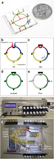
Given the nature of most microfluidic systems, they operate at small Reynolds number. This means that many operations, like mixing, are limited by diffusion. This can be slow and ineffective. As a result, microfluidics processes like DNA separation can be slow and inefficient [2]. One solution to this problem can be active mixing. Here, contrary to passive mixing, external forces are applied to the fluids in order to accelerate the mixing process. There is a wide range of methods to perform active mixing, including: acoustic waves, magnetic field, pressure perturbation, and thermal methods among many others. There is a method that uses circle-shaped channels to achieve the blending of fluids called a ring mixer seen on Figure 1. A big advantage bing that it allows for batch processing.
Ring Mixer
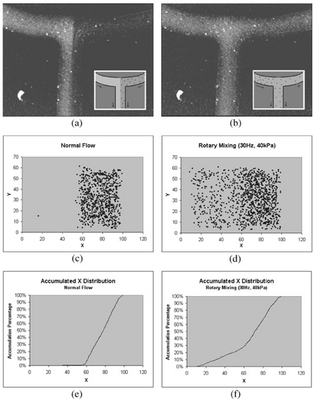
Ring mixers, also known as rotary pumps are a relatively simple form of active mixing where fluid solutions are actively pumped into a circulating loop. As seen in Figure 3, these can achieve up to about two orders of magnitude less time that other similar passive-mixing devices. Such devices display the following characteristics: 1) The fluid mixing is only improved along the direction of flow. The ring mixer is a very efficient "batch processor", were one or more homogeneous fluid plugs are injected into the ring (closed at the exit) where they can then mix by running with average velocity [math]\displaystyle{ U_0 }[/math] along the closed circle channel of radius [math]\displaystyle{ R }[/math] and height [math]\displaystyle{ h }[/math] to then exit when the exit valve is opened. 2) In convectively-stirred mixing regime [math]\displaystyle{ (Pe \gt \gt R/h) }[/math], the mixing time depends algebraically on [math]\displaystyle{ (Pe) }[/math] since the fluid elements are extended linearly in time [6].
Mixing Regimes

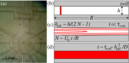
So, how fast does the fluid mix? It depends on how fast it flows. To quantify the mixing, there are three different regimes (as seen in Figure 2): (a) Diffusion-dominated, (b) Taylor dispersion-mediated, and (c) Convectively-stirred. Each one works as follows:
Diffusion-Dominated Mixing

For diffusion-dominated mixing, molecular diffusion plays the dominant role in tracer dispersion when the pumping velocity [math]\displaystyle{ (U_0) }[/math] is really slow. Therefore, it would rarely prove useful when mixing fluids. Here, mixing is achieved only after tracers diffuse around the circumference of the ring, requiring a time [math]\displaystyle{ \tau_R }[/math] [9].
\[ \tau_R \sim \dfrac{(2 \pi R)^2}{D} = \left(\dfrac{2 \pi R}{h}\right)^2 \tau_D \] Where:
- D = diffusivity of the fluid
- [math]\displaystyle{ \tau_D \frac{w^2}{D} }[/math]
- [math]\displaystyle{ w }[/math] = channel width
Taylor Dispersion-Mediated Mixing
Also known as Taylor-mediated mixing assumes the dominant role in axial dispersion if the flowrate is increased such that, [math]\displaystyle{ Pe\gt \gt 1 }[/math]. Here, axial spreading grows diffusively with Taylor dispersivity [math]\displaystyle{ D_z \sim \frac{U_0 ^2 w^2}{D} }[/math] :
\[ \tau_{TD} \sim \dfrac{(2 \pi R)^2}{D_z} \sim \dfrac{D(2 \pi R)^2}{U_0 ^2 h^2} \sim Pe^{-2} \tau_R \]
Molecules have to diffuse across the channel before convective stretching folds a stripe into itself in order for Taylor dispersion to dominate. Therefore, Taylor-dispersion-mediated mixing happens when Pe is falls in the range [math]\displaystyle{ (1 \lt \lt Pe \lt \lt \frac{(2R)}{h}) }[/math] [9].
Convectively-stirred mixing
If the flowrate becomes rapid enough a tracer stripe folds into itself multiple times before molecules diffuse across the channel. After a certain stirring time [math]\displaystyle{ (\tau_s) }[/math] fluid in the center makes N revolutions. A vertical stripe is elongated by the flow into a parabola, which in turn folds into itself an N amount of times. The distance between the neighboring stripes decreases according to the following equation
\[ h_{eff} \sim \left(\dfrac {h}{2N}\right) \]
In order for complete mixing to take place, molecules in the stripe have to exclusively diffuse across the distance [math]\displaystyle{ h_{eff} }[/math] which requires a time [math]\displaystyle{ (\tau_s \sim \frac {h^2_{eff}}{D}) }[/math]. Stirring continues until mixing wins, which happens when both time scales roughly concur [math]\displaystyle{ (\tau_s \sim \tau_h = \tau_{con}) }[/math] [9], where
\[ \tau_{con} \sim Pe^{-2/3} \left(\dfrac {\pi R}{h}\right)^{2/3} \tau_D \sim Pe^{-2/3} \left(\dfrac {h}{\pi R}\right)^{4/3} \tau_R \]
References
1. “HOME Microfluidic Flow Control.” Elveflow, Elveflow, 2019, https://www.elveflow.com/
2. Chou, HP., Unger, M.A. & Quake, S.R. Biomedical Microdevices (2001) 3: 323. https://doi.org/10.1023/A:1012412916446
3. Kong, David & A Thorsen, Todd & Babb, Jonathan & Wick, Scott & Jonathan Gam, Jeremy & Weiss, Ron & Carr, Peter. (2017). Open-source, community-driven microfluidics with Metafluidics. Nature Biotechnology. 35. 523-529. 10.1038/nbt.3873. https://doi.org/10.1038/nbt.3873
4. T. V. Nguyen, P. N. Duncan, S. Ahrar and E. E. Hui, Lab Chip, 2012, 12(20), 3991–3994. https://doi.org/10.1039/C2LC40466D
5. L. Dong and H. Jiang, Soft Matter, 2007, 3, 1223–1230. https://doi.org/10.1039/B706563A
6. M. Squires, Todd & R. Quake, Stephen. (2005). Microfluidics: Fluid physics at the nanoliter scale. Reviews of Modern Physics. 77. 10.1103/RevModPhys.77.977. https://doi.org/10.1103/RevModPhys.77.977
