Physics307L:People/Young/Formal2
Charge to Mass Ratio for an electron
Author: Daniel Young
Experimentalists: Arianna Pregenzer-Wenzler and Daniel Young
Location: UNM Department of Physics, Albuquerque, New Mexico, United States
Date of experiment: September 19, 2008
Abstract
To find out the charge over mass ratio of the electron beam we will introduce a constant magnetic field perpendicular to a beam of electrons created by an electron gun. The magnetic field will be controlled by a Helmholtz coil apparatus where the current through the coils and the accelerating voltage dictate the radius of the electron beam. First we will measure the various radii of the electron beam by varying the accelerating Voltage in the electron gun for a fixed magnetic field. Second we will vary the B field and measure the resulting radii. The magnetic field will be changed by changing the current through the coils solely. Thirdly we will vary both magnetic field and accelerating Voltage and measure their effects on the radii of the electron beam. With three different methods of measuring the e/m ratio we can weigh the effectiveness of each method to find the best possible charge to mass ratio.
My value for the e/m ratio tuned out to be.
- [math]\displaystyle{ \frac{e}{m}=2.051e11 \ }[/math] C/kg
While the current accepted value is
- [math]\displaystyle{ \frac{e}{m}=1.76e11 \ }[/math] C/kg
With the percent difference of 15% in mind, I believe that the value for e/m obtained in this lab is an excellent example of the effectiveness of our simple apparatus and the consistency of the accepted value. Most error was acquired during the acquisition of the data off of a reflecting ruler in the back and in order to improve this experiment I would create a more effective way of reading the electron path radius.
Introduction
SJK 16:19, 16 December 2008 (EST)

As noted previously, references to peer-reviewed research papers are necessary in this section.
In our experiment we hope to find an experimental value for the ratio of charge over mass for an electron. The electron charge over mass ratio is a well known value that we hope to confirm using the most practical methods available in out Lab. The electron is a fundamental building block of the atom. To understand more about the electron would mean a greater understanding of atoms and the interaction they undergo. Also the value of an electrons charge and mass is invaluable to other experimenters who wish to use electrons in any part of their experiment. According to The International Union of Pure and Applied Chemistry [page 96] the accepted value for the charge to mass ratio of an electron is 1.76*10^11 C/kg which was found by the experimental methods of Cohen and Taylor. In this paper I will be using my own methods and data analysis procedures to find the charge over mass ratio for an electron and compare it to the accepted value to determine the effectiveness of my method and ways to improve upon it.
Methods and Materials
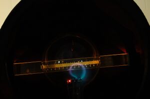
Materials
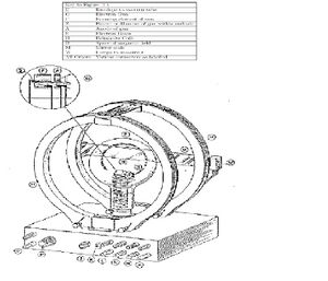
- 1 High Voltage power supply 5 kV max for the accelerating plates in the electron gun
- 1 Low Voltage supply voltage 2.5V for the Helmholtz Coils
- 1 Low Voltage supply not to exceed 6V for the Heater in the electron gun
- banana plugs
- multimeter to monitor current and Voltage
- air tight Helium gas filled bulb
- electron gun
- Helmholtz coils
Calibration
- All of the power supplies are connected to Voltmeters and Ammeters to ensure that the values we view on the power supplies are correct.
- if the bulb is turned too much one way or the other the beam can make a Helix rather than a loop so we made sure to line the beam up completely perpendicular to the appaeratus before taking measurements.
Derivation of e/m Relation to our input
Relation of charge over mass ratio using forces.
[math]\displaystyle{ F_e = ma \ }[/math]
[math]\displaystyle{ B_Hq = \frac{mv}{r} \ }[/math]
Relation of charge over mass ratio using Energy
[math]\displaystyle{ KE = eV \ }[/math]
[math]\displaystyle{ \frac{1}{2}mv^2 = qV \ }[/math]
Where,
- [math]\displaystyle{ V \ }[/math] is the accelerating Voltage in Volts
- [math]\displaystyle{ v \ }[/math] is the velocity of the electron in m/s
- [math]\displaystyle{ q \ }[/math] is the charge which in this case is the charge of an electron
- [math]\displaystyle{ m \ }[/math] is the mass of an electron which is
- [math]\displaystyle{ B_H \ }[/math] is the B field produced by the Helmholtz coils in (V s/m²)
- [math]\displaystyle{ r \ }[/math] is the radius of the electron beam path in meters
The general form of the equation for a Helmholtz coil is [math]\displaystyle{ B_H = \frac{\mu_0 I R^2}{2(R^2+x^2)^{3/2}} }[/math]
We will estimate that the value for x is about R/2 within for our electron beam.
After simplifying all of our equations we have
- [math]\displaystyle{ \frac{q}{m} = (\frac{5}{4})^3 \frac{2V(R^2)}{{\mu_0}^2 n^2 I^2 r^2} \ }[/math]
Where,
- [math]\displaystyle{ R \ }[/math] is the Radius of the Helmholtz coils which is .15 meters
- [math]\displaystyle{ \mu \ }[/math] permeability of free space 1.2566371 × 10⁻⁶ (N/A^2)
- [math]\displaystyle{ n \ }[/math] is the number of loops in the Helmholtz coils which is 130
- [math]\displaystyle{ I \ }[/math] is the current through the coils
Method
With power supplies powering the coils and the electron gun a beam of electrons can be observed. Starting with a fixed accelerating Voltage I slowly increased the current by .1A and record the changing radius of the electron beam for each current. For the second method I vary current in the Helmholtz coils and record the result radii when the accelerating Voltage is changed in increments of 10V. Finally for the third experiment I change both the current and Voltage to see their effect together on the radius. For all methods the radius was measured by a reflecting ruler behind the apparatus. By lining up the image of the beam with the actual beam I was able to ensure that my measurement was not distorted by my viewpoint. Using the relation derived in the previous section I found the value for q/m with a least squares fit of my data in matlab using the linear polyfit command. Figure 3 represents my data for the constant Voltage method, Figure two represents my the data for my constant current method and Figure three represents the data for the method in which both current and Voltage are varied.
SJK 16:27, 16 December 2008 (EST)

These figures are nice, especially how you include the accepted value slope...and the captions are good too. However, I am confused as to what the error bars represent and also how you do the accepted value line. This is because you don't really discuss the figures in the text of the paper (and you also refer to their numbers incorrectly) and the methods don't seem to describe these topics.
Vary Current
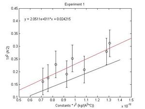
While keeping the Voltage constant we start with a large radius (High Current) and then lower the Current by small increments so we can measure the resulting radius of the electron Beam. Here the Magnetic field delegates the radius of the beam.
Since we are holding the Voltage constant.
- [math]\displaystyle{ r^2 \propto \frac{1}{I^2} }[/math]
Constant Voltage: 449.3V
| Current (A)±.01 | Radius(cm) | error in Radius(±cm) |
| 2.491 | 3.25 | .1 |
| 2.391 | 3.35 | .1 |
| 2.291 | 3.70 | .1 |
| 2.191 | 4.00 | .1 |
| 2.09 | 3.5 | .1 |
| 1.991 | 3.8 | .1 |
| 1.891 | 4.35 | .1 |
| 1.790 | 4.4 | .1 |
Vary Voltage
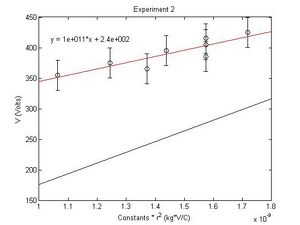
While holding the Current constant I start with a large radius (High Voltage) and lower the Voltage by small increments and measure the radius of the electron Beam. Here the tangential speed of the electron delegates the radius of the beam.
Since we are holding the Current constant.
- [math]\displaystyle{ r^2 \propto V }[/math]
Constant Current of 1.6A
| Voltage (V)±.1 | Radius(cm) | error in Radius(±cm) |
| 355 | 3.7 | .1 |
| 365.5 | 4.2 | .1 |
| 375 | 4 | .1 |
| 385.5 | 4.5 | .1 |
| 395 | 4.3 | .1 |
| 405 | 4.5 | .1 |
| 415 | 4.5 | .1 |
| 425 | 4.7 | .1 |
Vary Current and Voltage
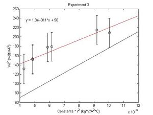
Now we vary both Helmholtz Current and Voltage.
- [math]\displaystyle{ r^2 \propto \frac{V}{I^2} }[/math]
| Voltage (V) | Current (A) | Radius (cm)±.1 |
| 449.2 | 1.292 | 4.3 |
| 421.1 | 1.400 | 5.5 |
| 401.6 | 1.503 | 4.4 |
| 390 | 1.605 | 4 |
| 380.4 | 1.7 | 3.75 |
| 395 | 1.606 | 4 |
| 405.5 | 1.506 | 4.5 |
| 415 | 1.410 | 5.75 |
The bold value in the table represents an outlier that was removed from the graph. It was the only value that was not within one standard deviation of the predicted slope.
Results and Discussion
All calculations were made using matlab functions. A least squares fit was used to find the values of the final ratios.
SJK 16:29, 16 December 2008 (EST)

Partially because your sigma and SEMs do not have units, I am completely confused as to what they represent. I don't really believe, based on your graphs, that the SEMs should be so different from each other.??? I also don't think it's possible with this apparatus to get anywhere near the accepted value, as relative to the uncertainty.
The accepted value for the e/m ratio is
- [math]\displaystyle{ \frac{e}{m}=1.76e11 \ }[/math] C/kg
Constant Voltage Vary Current
- [math]\displaystyle{ \frac{e}{m}=2.051e11 \ }[/math] C/kg
- σ=0.0526
- sem=0.0066
- %difference from accepted=15.53
Constant Current Vary Voltage
- [math]\displaystyle{ \frac{e}{m}=1.0227e11 \ }[/math] C/kg
- σ=24.408
- sem=3.051
- %difference from accepted=41.89%
Vary Current & Vary Voltage
- [math]\displaystyle{ \frac{e}{m}=1.2889e11 \ }[/math] C/kg
- σ=30.69
- sem=4.38
- %difference from accepted=26.77%
The value found in the first experiment leads me to believe that it is the most effective way of finding the e/m ratio. The accepted value falls within our 68% confidence interval of our data points. Also this method produced the best percent error and standerd error mean. Experiment 2 where only the current was varied produced the worst results.This leads me to believe that our the assumption of x=R/2 for the entire electron beam made a larger impact than originally predicted.
Analysis
Since Experiment 2 produced large standard deviations and ratios that fall outside of the 68% confidence interval I chose Experiment 1 and 3 to be the most effective methods. Using weighted means I will now find the best value for the two values found in the two experiments.
- [math]\displaystyle{ \bar{x} = \frac{w_1 x_1 + w_2 x_2 + \cdots + w_n x_n}{w_1 + w_2 + \cdots + w_n}. }[/math]
- [math]\displaystyle{ w_i = \frac{1}{\sigma_i^2}. }[/math]
Since the standard deviation for Experiment three is so much larger than the standerd deviation for the first experiment the weighing the means shows that the third experiment is negligible in finding the best data point. Therefore my final value will remain.
- [math]\displaystyle{ \frac{e}{m}=2.051e11 \ }[/math] C/kg
Conclusions
SJK 16:31, 16 December 2008 (EST)

The discussion of the beam width is good. However, I don't think the beam radius measurements are the significant systematic error in this apparatus.
The charge to mass ratio found through this method was very close to the accepted value considering the large unavoidable systematic error that occurs when reading measurements off of the reflection that the electron beam creates on the mirror ruler. As said previously, after analyzing the data I concluded that the best method was one where the current was varied. The accelerating voltage could have made a difference in the electron beam size where the Helmholtz coil current did not. The voltage plates seemed to have an effect on the beam width. If the beam width changed with the accelerating voltage then as the voltage increased a new piece of systematic error would exist that did not exist with the varying current method. This apparatus was very effective however, a more precise measurement system would be the next step to more accurate data and resulting values for the charge to mass ratio of an electron.
Acknowledgments
Much thanks to my lab partner,Arianna Pregenzer-Wenzler, through the thick and thin we bounced ideas off each other until things worked no matter how long it took. Thanks to Stephen Koch for giving us just enough information so we get through the lab yet still learn a lot about overcoming problems experimentalists experience every day. Thanks to the junior lab class of fall 2008 and spring 2008 for providing numerous excellent examples of lab reports and to Aram, for asking way too many thought provoking questions.
References
SJK 16:32, 16 December 2008 (EST)

As noted above, you needed some citations to original peer-reviewed research!
- Michael Gold, "The UNM Dept. of Physics and Astronomy PHYSICS 307L: Junior Laboratory"(Fall 2006),experiment 5 (page 31-40)
- Taylor, "An Introduction to Error Ananlysis, 2nd edition" (1997, University Science Books), page 174-176
- As discoverd through wikipedia, International Union of Pure and Applied Chemistry. "mass-to-charge ratio". Compendium of Chemical Terminology Internet edition.[electronic version]