Modrilla
If you're just looking for the Modrilla software, go to http://web.mit.edu/wgrover/www/modrilla.html. For instructions on how to use Modrilla and a Modela mill to drill holes in glass, read on...
Overview
Modrilla is Java software for drilling holes in glass wafers using a CNC mill or a Roland Modela rapid prototyper.
Modrilla is most useful if:
- you have a lot of holes to drill,
- manual drilling isn't accurate enough, or
- you need holes in a certain pattern on an otherwise-featureless wafer, making manual drilling difficult.
Modrilla is less useful if you only have a few holes to drill (preparing your CAD file and setting up the Modela takes some time) or if your tolerance requirements aren't too precise; in these cases you should just drill the glass by hand using a high-speed drill (like a Dremel tool) mounted in a drill press. If you're drilling by hand, you may find Preparing the glass piece useful.
What you'll need
- The "good" piece of glass you want to drill.
- A "junk" backing piece of glass, ideally the same kind of glass as your "good" piece of glass, but cheap microscope slides usually work well, too.
- Pine resin for bonding the "good" piece of glass to the "junk" backing piece of glass
- A diamond-tipped drill bit with a 1/8" diameter shank (same size as Dremel tool bits) to fit into the mill. McMaster-Carr sells a variety of these; search for "diamond grinding points."
- A CNC mill that can run G-code, or a Roland Modela rapid prototyper.
- A DXF file describing the locations of the holes to be drilled (see next section.)
Preparing the DXF file

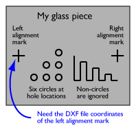
You'll need a DXF file with circles placed at the locations where you want holes to be drilled--all circles in the file will be drilled, so make sure that there are circles only where you want holes. Lines, polylines, etc. are ignored. Units for the DXF file can be microns, mm, cm, mils, or inches, and the absolute locations of the holes don't matter, as long as their arrangement relative to each other is correct. Most any program can be used to generate the DXF (AutoCAD, Adobe Illustrator, etc.).
If you're drilling holes into an otherwise-featureless piece of glass, then that's all you need to prepare for drilling. However, if your holes are relative to existing features on your wafer (etched channels, metalization, etc.), then you need to know the coordinates of two alignment features already on your wafer. These are used to align the mill to the wafer in preparation for drilling. These marks can be any visible features on the wafer; they should be as far apart as possible and on the same horizontal line (same Y coordinate) in the DXF file when you view it in something like AutoCAD. You need to know the coordinates of the first mark from the DXF file.
Preparing the glass piece
Temporarily bonding your "good" piece of glass to a "bad" backing piece of glass improves the quality of the drilled holes. It's possible to drill glass without a backing piece of glass, but you might as well use a BB gun. Pine resin or "rosin" is a good temporary adhesive because it's cheap and easily soluable in acetone. Sigma sells it as Alfa Aesar stock number 36734, CAS number 8050-09-7.
- Place a piece of aluminum foil on a hotplate, place your "bad" piece of glass on the foil, and heat the hotplate to around 150 C.
- Grind the pine resin in a mortar and pestle and add drop some powdered pine resin onto the "bad" glass. It should melt, bubble up a bit, and eventually calm down to form a yellowish pool of melted pine resin. If it smokes, your hotplate is too hot.
- Place your "good" glass wafer on top of the melted pine resin. Using a piece of wood wrapped in aluminum foil, slowly press the "good" wafer, pushing extra pine resin and any air bubbles out from between the two pieces of glass. Keep pressing until few if any air bubbles remain trapped between the two pieces of glass.
- Using the aluminum foil, lift the glass pieces from the hotplate and set them aside to cool.
Placing the glass piece on the mill
(For Modela-specific instructions, see the next section)

- Install your bit. Make sure the bit will be able to reach the stage where the glass will be. This isn't a problem with longer bits, but short bits may not be able to reach.
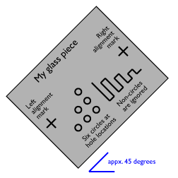
- Place your stack of glass pieces on the mill's platform, rotated about 45 degrees counterclockwise from the orientation of the glass in your DXF file. See the figures for an example. This angle is not precise, just roughly 45 degrees. (Why rotate? Orienting your glass at an angle [math]\displaystyle{ \theta }[/math] such that [math]\displaystyle{ \sin \theta }[/math] and [math]\displaystyle{ \cos \theta }[/math] are between 0 and 1 and [math]\displaystyle{ \tan \theta }[/math] is approximately 1 simplifies the trigonometry involved in converting the hole locations from the DXF file's coordinates to the mill's coordinates.) Make sure that all hole locations fall within the mill's range of motion (the grid pattern printed on the platform).
Placing the glass piece on the Modela
This part assumes that you're already moderately familiar with operating the Modela. For generic Modela information check out the MAS 863 Modela instructions.
- Turn on the Modela by pressing the green Power button.
- Install your bit. Make sure the bit will be able to reach the stage where the glass will be. This isn't a problem with longer bits, but short bits may not be able to reach.
- Place your stack of glass pieces on the Modella's platform, rotated about 45 degrees counterclockwise from the orientation of the glass in your DXF file. See the figures for an example. This angle is not precise, just roughly 45 degrees. (Why rotate? Orienting your glass at an angle [math]\displaystyle{ \theta }[/math] such that [math]\displaystyle{ \sin \theta }[/math] and [math]\displaystyle{ \cos \theta }[/math] are between 0 and 1 and [math]\displaystyle{ \tan \theta }[/math] is approximately 1 simplifies the trigonometry involved in converting the hole locations from the DXF file's coordinates to the mill's coordinates.) Make sure that all hole locations fall within the mill's range of motion (the grid pattern printed on the platform).
- Turn off View mode by pressing the View button.
Running Modrilla
- Run Modrilla 2.0 at http://web.mit.edu/wgrover/www/modrilla.html.
- Follow the prompts that Modrilla provides. I'll include more detail here soon.
- In the end Modrilla will create a new file in the same directory where your original DXF file is located. The new file will either end in "ngc" (G-code to run on your mill) or "sh" (a shell script for running on the computer to which your Modela is connected).
Drilling your glass
- Cover the rest of the glass piece with a small puddle of water. Make sure that all hole locations are covered with water; dry-drilling a hole in glass ruins the drill bit and usually ruins the glass piece, too. Using a dropper and a careful hand, it's possible to cover the entire "good" piece of glass without having the puddle of water run down onto the mill.
- Load and run the generated G-code file using your mill's software.
- When everything's done, use a dropper to remove most of the water (which now contains ground glass and is very abrasive, so avoid rubbing it against the surface of your glass piece). Remove your glass pieces from the Modela's platform and rinse off the remaining ground glass.
- Place your glass pieces back on a piece of aluminum foil on a hotplate. Once the pine resin between the glass pieces has melted, use a screwdriver or tongue depresser to push the "good" wafer off the "bad" backing wafer and onto the aluminum. Then lift both glass plates by the aluminum and set them aside to cool. Finally, remove the remaining pine resin from the "good" wafer using acetone from a squirt bottle.