Electrowetting Valves - Davis Miller, Sarthak Saha
Introduction

Currently, one of the largest issues with microfluidics is that devices are complex and require much outside equipment, such as pumps to drive flow[1]. Ideally, these devices would be portable and usable in locations with limited resources, acting as a point-of-care-device[1]. One alternative method to flow in a microfluidic device that is being investigated is capillary flow. This removes the need for outside assistance in fluid flow, as capillary action is intrinsic to the system. By modifying the surface of the channels to be hydrophobic or hydrophilic, this flow may be controlled. Furthermore, hydrophobic valves may be installed to stop flow at desired locations, and then by applying a voltage, these valves are "opened" due to the change of the surface to being hydrophilic. This is known as an electrowetting valve.
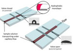
The phenomenon of electrowetting has been around for quite some time. The origins of modern electrowetting theory has its roots in the work of Gabriel Lippmann in 1875[4]. He found that the capillary depression of mercury in contact with an electrolyte solution could be changed with an applied voltage. Additionally, it has been shown that the contact angle of water on a surface can be changed due to spontaneous movement of charges. In microfluidics, an electrowetting valve is a novel approach to controlling fluid flow. A basic schematic may be found in Figure 1. It takes advantage of the effects of an electric field on the wetting properties of a surface. Typically, the surface is hydrophobic, preventing flow at this barrier due to surface tension of the fluid. By applying an electric field to the surface, the chemistry can be modified, becoming hydrophilic and allowing flow. These surfaces most commonly consist of a silver electrode that has been modified with a monolayer of polytetrafluoroethylene (PTFE)[1]. PTFE is hydrophobic, but when applying an electric field, it becomes polarized and therefore hydrophilic. Capillary flow then resumes in the channel. The surface that these electrodes are printed on can vary, glass and flexible substrates like PET have been reported. Surface contamination and various factors of the substrate effects the wetting nature of the silver ink. This in turn affects the droplet wettability and voltages required.
The following is a video demonstrating an electrowetting valve controlling fluid flow.
Theory

The electrowetting phenomenon is described as when the contact angle between an electrolyte and solid decreases as a result of an applied electric field (see Figure 2) This is because the surface tension is altered in the presence of this electric potential. This may be demonstrated by examining the forces acting on the droplet. Forces present from the applied electric field act to "pull" the corners of the droplet down onto the electrode, reducing contact angle.
Alternatively, as has been described by Kang et al., this phenomenon may be viewed from a thermodynamic perspective. Considering the minimum free energy requirement for thermodynamic equilibrium, the electrowetting equation becomes:
[math]\displaystyle{ cos(\theta)=cos(\theta _{o})+ \frac{\epsilon V^{2}}{2\gamma _{12}d} }[/math]
where [math]\displaystyle{ \theta _{o} }[/math] is the contact angle without the electric potential, [math]\displaystyle{ \theta }[/math] is the contact angle with a potential of [math]\displaystyle{ V }[/math] applied, [math]\displaystyle{ \epsilon }[/math] is the electric permittivity of the dielectric layer, [math]\displaystyle{ \gamma _{12} }[/math] is the interfacial tension between the droplet and solid, and [math]\displaystyle{ d }[/math] is the dielectric layer thickness[2]. This equation is what is known as the Lippmann-Young equation. From this equation it is clear that voltage required to change contact angle depends heavily on the dielectric constant of the surface (the electric permittivity) in addition to the thickness of the layer. This typically results in high voltage requirements to sufficiently change contact angle and drive flow[8].
Essentially, the addition of a voltage at the interface between a liquid and dielectric acts to reduce the interfacial tension between the two, resulting in a reduced contact angle (increased wettability). This happens due to the redistribution of charges and dipoles, changing the surface energy at the interface[8].
Fabrication and Current Performance
Considering the science of operation, there are two type of devices available in the literature. The first uses electrowetting on bare electrode while the other uses the concept of 'Electrowetting on Dilectric' (EWOD).
Earliest work was done by Suzuki Labs in 2008 [9] where gold was sputtered on a glass substrate to be used as an electrode and its wettability was tweaked to actuate flow. Interestingly gold electrodes are predominantly hydrophilic and hence should not be able to stop the flow of liquid. The authors report when the gold electrodes were exposed to atmospheric condition, a contamination layer of carbonaceous compound was deposited which gave hydrophobic characteristics to the film. The wettability of the electrode could be changed by applying a very low potential of -0.9V. In their subsequent work they incorporated several complications while using the same gold electrode.
Firstly the use of pH electrode[10] which gives control over the valve based on the pH of the incoming solution thus creating a pH sensitive valve. This is accomplished using a iridium oxide reference electrode, where the potential becomes negative when pH increases. The valve is actuated when constant voltage is applied between the gold and pH sensitive electrode.

Work reported in 2012[11] describes an autonomous device where a zinc electrode was connected parallel to the gold valve, utilising the concept of mixed potential the gold valve could be opened to actuate flow. Here, "mixed potential" means the net potential in the cathode and anode is zero due to the presence of various redox reactions that convert the electrical potential into chemical products at the two electrodes. Hence when the solution reaches zinc electrode it actuates flow via electrowetting in the gold electrode by changing the potential. Thus these devices do not need any outside source of potential. The same lab reported an intricate device in 2013[12] combining the zinc electrode and pH sensitive hydrogen electrode while using their signature gold electrode for the valve.
In most of the reports, salt solutions like KCl, NaCl, LiCl and others are used to measure changes in the contact angle because unlike water the electrolysis of these liquids requires a really high potential . Washe et al. [13] reported a detailed comparison of the various salts and their effect on the changes in contact angle. Their work was particularly unique as they use superhydrophobic nanoporous carbon based electrode which did not require any hydrophobic coating, as the patterns hold water droplet in Cassie-Baxter region (contact angle 151°). Upon applying potential across the droplet, wettability transitions to Wenzel state thus wetting the surface.

Nardecchia et al. (2018)[14] reported valve which uses the traditional concept of EWOD. They used three layers to create both the top and bottom part of the device. In both part dielectric layer made of SU-8 was surrounded with electrode on one side and a hydrophobic coating of teflon on the other. The bottom part had the conductive electrode made of chromium and aluminium, while top used indium based tin oxide (ITO). These two were joined with SU-8 channels in the middle thus forming the electrowetting valve. This device required really high actuation voltage, as compared to previously mentioned devices, the incorporation of three different layer induced higher capacitance, thus resulting in a large actuation potential of 35V.
The Nugen group used the concept of EWOD but improved upon previous voltage requirements by incorporating a very thin layer of hydrophobic coating which forms a self-assembled monolayer. The monolayer is considered to behave as the dielectric whose capacitance depends on the thickness off the layer. This valve has then been incorporated into two basic kinds of devices – sandwich[1] and lateral flow assay[7]. The sandwich design uses polyethylene teraphthalate (PET) as the substrate which, is inherently hydrophobic and thus needs to be treated with UV/ozone to induce hydrophilicity. Inkjet printed silver electrode modified using 1H,1H,2H,2H-Perfluorodecanethiol (PFDT) or PTFE in deoxygenated absolute ethanol solution is a signature fabrication method used in all the works reported by Nugen Lab. Silver electrodes were inkjet printed, modified using 1H,1H,2H,2H-Perfluorodecanethiol (PFDT) in deoxygenated absolute ethanol solution and this a signature method in all the reported works of Nugen Lab. It creates a self-assembled monolayer hydrophobic coating on the silver electrode. The critical improvement in the devices reported by the Nugen lab is the ultra-thin nature of the dielectric layer, which have lower capacitance and hence required low potentials of 2-4V [1].
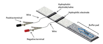
In 2013 the Nugen group tried incorporating electrowetting into paper microfluidics [7](Figure 4) using lateral flow assembly. Both hydrophobic and hydrophilic silver inks were created to define the two electrodes. The test assembly was a plastic base and a nitrocellulose paper layer adhered by double sided tape. The liquid droplet crossed the 1st hydrophilic silver electrode and stopped at the PDFT modified Silver. A potential of 16V was required to actuate the flow by destroying the monolayer.
Challenges
The major challenge currently associated with electrowetting valves is the fact that these devices are one-time actuation devices, meaning that once the valve is opened, it cannot be closed again. This is a result of what is known as the breakdown voltage, meaning the amount of voltage applied that results in a permanent change to the material, in this case hydrophilicity. This voltage is usually required in order to induce a significant contact angle change to drive flow. The breakdown voltage does change with dielectric thickness, so it is theoretically possible to modify the materials so as to have a reversible wettability. However, it is not clear whether this has been or can be achieved[8].
References
[1]Marian, T., He, F., Yan, H., Chu, D., Talbert, J. N., Goddard, J. M., & Nugen, S. R. (2012). Development and surface characterization of an electrowetting valve for capillary-driven microfluidics. Colloids and Surfaces A: Physicochemical and Engineering Aspects, 414, 251–258. doi:10.1016/j.colsurfa.2012.08.020
[2] Kang, Kwan Hyoung. "How electrostatic fields change contact angle in electrowetting." Langmuir 18, no. 26 (2002): 10318-10322.
[3] He, Fei, Jeff Grimes, Samuel D. Alcaine, and Sam R. Nugen. "A hybrid paper and microfluidic chip with electrowetting valves and colorimetric detection." Analyst 139, no. 12 (2014): 3002-3008. DOI: 10.1039/c3an01516e
[4] Mugele, F., & Baret, J. C. (2005). Electrowetting: from basics to applications. Journal of Physics: Condensed Matter, 17(28), R705.
[5] By Juan Ignacio Polanco - Own work, CC0, https://commons.wikimedia.org/w/index.php?curid=29626856
[6]]Cheng, J. Y., & Hsiung, L. C. (2004). Electrowetting (EW)-based valve combined with hydrophilic Teflon microfluidic guidance in controlling continuous fluid flow. Biomedical microdevices, 6(4), 341-347. doi:10.1023/B:BMMD.0000048565.59159.c1
[7] Koo, C., He, F., and Nugen, S. An inkjet-printed electrowetting valve for paper-fluidic sensors. Analyst 138, (2013): 4998–5004. DOI: 10.1039/c3an01114c
[8] Moon, H., Cho, S. K., Garrell, R. L., & Kim, C.-J. C. J. (2002). Low voltage electrowetting-on-dielectric. Journal of Applied Physics, 92, 7, 4080-4087.
[9] Satoh W, Yokomaku H, Hosono H, Ohnishi N, Suzuki H. Electrowetting-based valve for the control of the capillary flow. J Appl Phys 2008;103:034903.
[10] Yamaguchi S, Morimoto K, Fukuda J, Suzuki H. Electrowetting based pH- and biomolecule responsivevalves and pH filters. Biosens Bioelectron 2009;24:2171–2176.
[11]K. Kojima, M. Yokokawa and H. S. Graduate, "Autonomous microfluidic control by mixed potentials generated on composite metal electrodes," 2013 Transducers & Eurosensors XXVII: The 17th International Conference on Solid-State Sensors, Actuators and Microsystems (TRANSDUCERS & EUROSENSORS XXVII), Barcelona, 2013, pp. 396-399.
[12]Kojima K, Yokokawa M, Suzuki H. Microfluidic ionresponsive channels based on electrowetting. Sens Actuators B Chem 2013;177:929–935.
[13] Washe, A. P., Lozano, P., Bejarano, D., & Katakis, I. (2013). Eletrochemically Actuated Stop–Go Valves for Capillary Force‐Operated Diagnostic Microsystems. ChemPhysChem, 14(10), 2164-2173.
[14] Nardecchia, M., Llorca, P. R., de Cesare, G., Caputo, D., Lovecchio, N., & Nascetti, A. (2016, February). Design, Fabrication and Testing of a Capillary Microfluidic System with Stop-and-Go Valves Using EWOD Technology. In Convegno Nazionale Sensori (pp. 200-208). Springer, Cham.
[15]Zhang, D., Wang, L., Qian, H., & Li, X. (2016). Superhydrophobic surfaces for corrosion protection: a review of recent progresses and future directions. Journal of Coatings Technology and Research, 13(1), 11-29.
