Droplet Microfluidics: Merging Droplets- Sanket Sabnis
Introduction
Reaction engineering is an important application of droplet microfluidics. A fine control over of one reagent into another can be achieved, by controlling the merging of the droplets containing those reagents. Droplet merging can be used to monitor reactions and study synthesis conditions, kinetics, crystallization parameters, proteins and biomolecule synthesis, or formation of particles. For some reactions, the order of the addition of reagents is critical. This can be achieved by containing each reagent in a separate droplet and merging the droplets at an appropriate time. Since droplet merging can affect the selectivity of a reaction, crystal size and morphology or particle size, it needs to be a highly controlled process. Passive of active methods can be used to control droplet merging. Passive methods do not rely on peripheral power sources or components. On the other hand, active methods use external power or electrical control to merge the droplets.
Passive merging
In passive merging, the microfluidic channel geometry is used to control the location of droplet merging1.
Droplet frequency
Merging of droplets depends on the frequency of droplet generation, which can be controlled by controlling the flowrate and diameter of the channel. If frequencies of the droplets match, they will coalesce at the junction.2
Channel obstruction
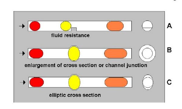
Merging can be achieved by introducing a fluid resistance in the cross-section of the fluid channel. This would result the droplets to stop, fuse and then get released. For this process to be well-controlled, the flow rate of the streaming sequence needs to be adapted to the properties of the trap/resistance.3 A trap should be able to change the shape of a droplet, which is responsible for the stopping and the subsequent merging. Three types of traps can be used: a hindrance inside the channel, a locally enlarged diameter of fluid channel, or a local asymmetry in the cross-section shape (Fig 1).
Changing surface-properties of the channel

Microdroplet formation and stability depends on the interfacial energies between the different phases as well as the channel walls. Changing the surface-energy of the channel wall result into instabilities in the droplets, which are exploited for the merging process. A patch of poly(acrylic acid) is grafted on a PDMS channel.4 When droplets flow past the hydrophilic patch, they get trapped. When more than one droplet is trapped, they merge effectively (Fig 2). When the viscous drag force on the droplet overcomes the surface energy stabilization, the droplet is released. The rate of merging can be controlled by controlling the periodicity of the droplets.
Channel junction expansion
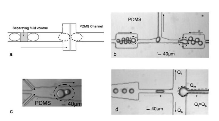
Coalescence can also be achieved by expanding the channel junction as shown in Fig 3(a). Three examples of expanded channel geometries are shown in Fig 3(b)-(d). Droplet merging in the straight expansion works at a limited range of rates and sizes determined by the length and width of the expansion. The tapered expansion, which is a series combination of straight expansions, works at a wider range of sizes and rates. However, undesired multiple merging can occur. A trifurcating junction allows fluid volume between the drops to be separated at controllable rates. On the other hand, the other two designs provide fixed rates based on the width of the expansion.5,6
Drainage of the continuous phase
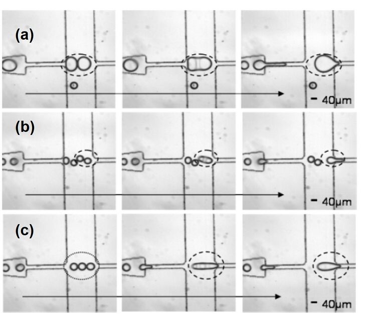
When droplets are generated at a specific periodicity, they are separated by an equal and finite volume of oil phase (continuous phase) that varies according to the droplet size and generation rate. For merging two or more droplets in a channel, the continuous phase separating them must be removed. When two droplets come into close contact, a thin liquid bridge forms between the droplets due to the attractions between molecules. The high curvature meniscus formed around the bridge creates an imbalance of the surface tension that quickly coalesces the droplets. To form the initial contacts between droplets, the fluid between the droplets must be removed. The draining of this separating oil volume allows the droplets to be hydrodynamically trapped and they eventually fuse. A trifurcating junction is used to drain the continuous phase (Fig 3d). The rate of coalescence of the droplets can be controlled by controlling the ratio between the droplet transport time across the trifurcating junction and the drainage time of the fluid volume separating the droplets.7 The separating fluid volume flows into the upper and lower channels at a rate controlled by the resistance of the identical upper and lower channels. This allows equal fluid volume to be removed by the upper and lower channels. This design can be used for controlled merging of two or multiple droplets (Fig 4).
Active merging
Active methods rely on external power or electrical control to achieve droplet merging.
Controlled electrocoalescence
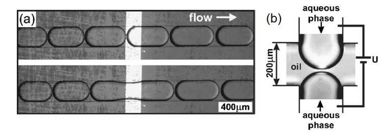
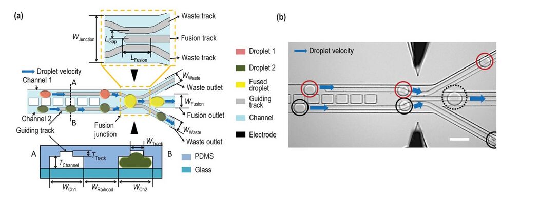
Subjecting adjacent droplets to a high electric field creates dynamic instabilities in the interface between the droplets leading to coalescence. Figure 5 shows aqueous droplets dispersed in an organic liquid and gold electrodes are shown as black rectangles.8 When a short pulse (100 ms) of 1 V dc is applied between the electrodes, the droplets that approach the electrodes coalesce. Since the merging is highly localized, it can be used to selectively merge pair of droplets. Electrocoalescence is attributed to the electrode geometry and the applied electrode potential. The potential should be optimized- it should be sufficient to rupture the interfacial lamella. Very high applied potential can lead to excessive coalescence through the channel length. The optimized potential is typically linearly dependent on the distance between adjacent droplets. Figure 6 shows a device which uses flow controlled by channel geometry in addition to electrofusion to merge droplets.9 Railroad-like structures are embedded in two parallel channels so that the droplets have the same velocities, which increases their chances of merging. At the junction, the railroad-like structures are removed and the two parallel channels unite into one fusion outlet. Waste outlets are provided to drain off the droplets that do not merge. Two electrodes are placed on the sides of the fusion junction and ac voltage is applied across them. Once two synchronized droplets exiting the channels touch each other, they will be merged using electric force. This method can be very effective to carry out reactions by merging a pair of droplets each containing a reagent flowing through the two parallel channels.
Dielectrophoresis
When a droplet is subjected to a non-uniform electric fluid ans when the dielectric constants of the drop and the surrounding medium are different, the electric stress acting on the drop's surface generates a net electric force called as dielectrophoretic (DEP) force.10 Under nonuniform electric stresses, droplets deform and move; the deformation increases as the drop moves closer to the electrodes. Figure 7 shows maneuvering of four aqueous droplets across two-dimensional electrode arrays suing DEP forces.11 The movement of the droplets is controlled by switching a series of electrodes on and off in sequence. Energizing an electrode adjacent to a droplet moves the local field energy minimum to that electrode. This exerts a lateral force on the droplet causing it to move in the direction of the new field minimum. A droplet can thus be guided toward another droplet until coalescence occurs.

Heating from a focused laser
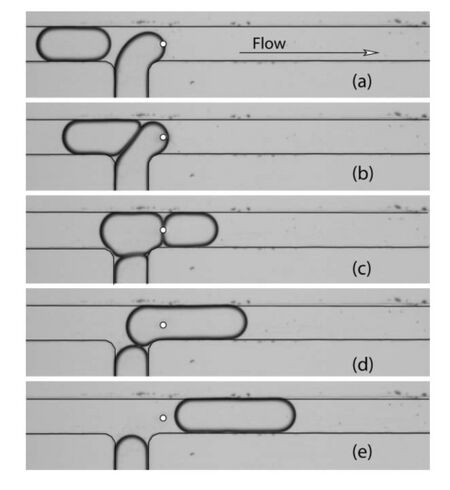
Local heating from a focused laser can apply a thermocapillary force on a liquid interface and can be used to block the movement of a droplet in a microchannel.12 Figure 8 depicts droplets forming at a laser junction. In the absence of the laser, the droplets are not synchronized and do not come in contact with each other, hence do not merge. The laser holds the the interface of the downstream droplet in place until the upstream drop approaches and collides with it. When the hydrodynamic drag on the two-drop system becomes very high, the droplets begin to flow again. When the touching interfaces of the droplets approach the laser point, they merge.
References
1. S.Y. Teh, R. Lin, L.H. Hung, A.P. Lee, Lab Chip, 2008, 8, 198-220. [1]
2. Y. P. Hong and F. J. Wang, Microfluidics Nanofluidics, 2007, 3, 341–346.[2]
3. J. M. Kohler, T. Henkel, A. Grodrian, T. Kirner, M. Roth, K. Martin and J. Metze, Chem. Eng. J., 2004, 101, 201–216.[3]
4. L. M. Fidalgo, C. Abell and W. T. S. Huck, Lab Chip, 2007, 7, 984–986. [4]
5. Y. C. Tan, J. S. Fisher, A. I. Lee, V. Cristini and A. P. Lee, Lab Chip, 2004, 4, 292–298. [5]
6. Y.-C. Tan, Y. Ho and A. Lee, Microfluidics Nanofluidics, 2007, 3, 495–499. [6]
7. K. Liu, H. J. Ding, Y. Chen and X. Z. Zhao, Microfluidics Nanofluidics, 2007, 3, 239–243.[7]
8. C. Priest, S. Herminghaus, R. Seemann, Applied Physics Letters, 2006, 89, 134101-3. [8]
9. L. Xu, H. Lee, R. Panchapakesan, K.W. Oh, Lab Chip, 2012, 12, 3936-3942. [9]
10. P. Singh, N. Aubry, Electrophoresis, 2007, 28, 644-657. [10]
11. J.A. Schwartz, J.V. Vykoukal, P.R.C. Gascoyne, Lab Chip, 2004, 4, 11-17. [11]
12. C.N. Baroud, M.R.S. Vincent, J.P. Delville Lab Chip, 2007, 7, 1029–1033. [12] ]