Design Tips and Flow Considerations - Savannah Szemethy
Overview of Microfluidic Art Design/Creation Process
The design tips and flow considerations described on this page are intended for use in conjunction with the photolithography/soft lithography design and creation process for microfluidic devices.
First, an artwork is sketched by hand or in Adobe Photoshop. Then, Adobe Illustrator is used to vector over the design in order to ensure that the design will be to scale. After finalizing the design in Illustrator, the design file is printed as a high-resolution photomask.
The photomask is brought into a clean room, where photolithography is then performed. As part of the photolithography process, layers of photoresist are spin-coated and baked onto a silica wafer. The final layer of photoresist is exposed to UV light, baked, and developed in order to transfer the design to the wafer.
A batch of polydimethylsiloxane (PDMS) is mixed in the proportions specified by the manufacturer and then vacuumed for 30 min - 2 hours in order to remove all air bubbles. Next, the vacuumed PDMS mixture is poured onto the silica wafer and baked around 75 C for about an hour. Once solidified, the area of the PDMS with the design is cut out, and inlets are drilled at their appropriate locations. The cut PDMS is then plasma-fused to a glass slide for 2-3 minutes in order to create the microfluidic chip.

Adobe Illustrator Design Considerations
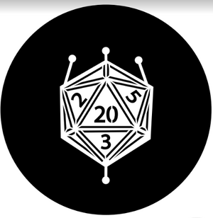
When designing microfluidic artwork in Adobe Illustrator, a black circle with the dimensions of the silica wafer should be used as the background layer. The design features themselves should be vectored in white so that they will be transparent when the final photomask is printed.
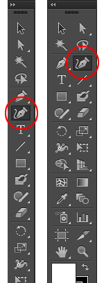
For ease of vectoring, it is recommended to use the Curvature tool as opposed to the general Line tool. Unlike the Line tool, which draws in straight line segments that must be manually joined, the Curvature tool allows the user to draw continuous segments that automatically are connected to each other and follow the curves of the tracing template.
Because these designs are artistic, it is ideal to make them as big as possible within the constraints of the wafer and glass slide used to create the final chip. The silica wafers are typically 3"x3", but glass laboratory slides are commonly 2"x3", so the glass slide dimensions are the biggest constraints.
Design features in Adobe Illustrator can be as small as 50 microns. The smaller the channels, however, the harder it is to visualize them in the final artwork. Features around 200 microns or higher are ideal for these artworks because they are clearly visible with the naked eye and photograph well.
If gradients are desired, multiple inlets should be included so that a variety of fluid colors can be used. Additionally, the channels should comprise the background of the image so that most of the design will be in color once filled, which allows for an adequate surface area for diffusion and mixing.
Depending on the complexity of the design, multiple outlets may need to be included. If a design has features on the order of 200 microns or higher that are not connected to an outlet, the features act as “dead ends” and don’t fully fill because they are not on the path of least resistance. This problem can easily be solved by including an outlet anywhere in the design that appears to act as a dead end.

Prevention and Reduction of Flooding

Flooding is large risk when creating microfluidic art using PDMS because of how little bonded surface area can exist between the PDMS and the glass, depending on the complexity of the design. If precautions are not taken, the entire chip can flood and completely obscure the design features, ruining the hours of work required by the soft lithography fabrication process. After plasma-fusing the PDMS to the glass slide, the completed microfluidic device should be baked on a hot plate set to 65-75 C for at least 30 min in order to heat-set and thus strengthen the plasma bond.
Inlets are particularly susceptible to flooding. After drilling an inlet, small chunks of scrap PDMS might aggregate within and around the hole. If the inlets are not properly cleared before plasma fusing the PDMS to the glass slide, the debris can be pushed through the small channels and potentially agglomerate, blocking flow in a similar fashion to a dam. As a result, the device will flood. To prevent this, inlets should be poked with a needle after drilling in order to push any PDMS scraps out of the opening. Scotch tape can then be applied and removed from the piece of PDMS in order to clear away any excess debris.
Precise control over flow rates, as described below, will also reduce flooding.
Flow Rates
Due to the intricacy of aesthetic microfluidic chips, a precise liquid dispensing pump should be used when filling the devices. These devices benefit from lower flow rates, typically those of 3 mL/hr or under, in order to reduce flooding. The rate of 3 mL/hr is typically the average flow rate that these devices can handle. Anything above 5 mL/hr is likely guaranteed to flood. Flow rates of 1 mL/hr are ideal for the creation of gradients because they increase the fluids' contact time in the channel.
Gradients and Swirling

As previously mentioned, gradients can easily be created by contacting two different colored fluids using flow rates of 1 mL/hr or under. Swirling patterns, however, can be more difficult to create because they rely on the creation of more turbulent flow. To do so, after the microfluidic device is completely filled, the pump can be paused, and the PDMS of the device can be poked with tweezers to disrupt and move colors out of their typical flow patterns. Then, when the device is restarted, the flow will push the disrupted colors through the device, creating a swirling effect. Swirling can also be achieved by pausing the pump to swap the position of inlet colors and then restarting the pump with the colors in different locations.
Photography
If creating devices using a standard 2"x3" glass slide with features of around 200 microns, then a high-quality cell phone camera (~12 megapixels) or a standard photography camera should be used in order to capture the entire artwork. If focusing on capturing brillance of color, the device should be photographed against a bright white background with adequate lighting.
When using a cell phone, the image should be photographed at a slight angle rather than head-on in order to reduce glare. The brightness setting on the camera app should be slightly increased before photography because the images will appear slightly darker on the computer than on the cell phone screen. The phone should be held at least 5-6" away from the device for the best focus.
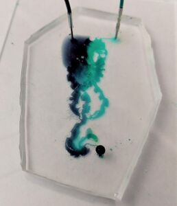
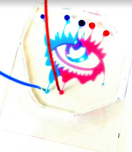
The Dark Mark and Eye images on the right of this page demonstrate how more careful attention to lighting greatly changes the impact of a picture. Note the difference in color quality and clarity between the two images. The Eye image is much more eye-catching. The Dark Mark device was quickly photographed in poor room lighting without any adjustment to the cell phone's camera lighting. The Eye device, however, was photographed in bright, fluorescent lighting with a slight increase to the phone camera's brightness, greatly increasing the final image quality.
References
1. Chelius, C. Using the Curvature Tool in Adobe Illustrator. https://creativepro.com/curvature-tool-adobe-illustrator/ (accessed Apr 10, 2019).
