Biomod/2011/Caltech/DeoxyriboNucleicAwesome/AFM Experiments
|
Thursday, January 29, 2026
|
AFM Experiments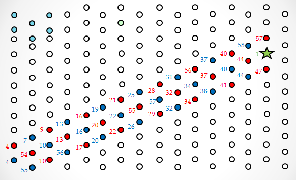
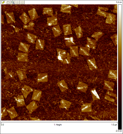
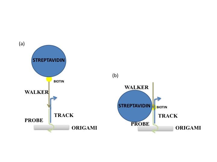 One hypothesis is that the streptavidin stock was bad or for some reason was not binding properly to DNA. To prove this was not the case, we ordered a biotinylated staple (green dot in Figure 1). The streptavidin was seen as a very bright spot on most origami. We decided to use the staple in all future AFM experiments as a control. A second hypothesis was that the insertion mechanism was not working, and that the walker was floating in solution. This seems unlikely, because free floating wakers could diffuse to the goal when triggered, but the fluorescence experiments showed that in the absence of tracks, walkers did not reach the goal. In any case, this hypothesis was tested by inserting another biotinylated staple at SP10. The streptavidin can be seen but less frequently than the biotinylated control staple. This low frequency could simply be due to stoichiometric differences, since in Figure 7 we see that the control staple appears on almost all origami, whereas before it was absent in many. A third hypothesis was that the streptavidin is too high from the surface on DNA with multiple nicks that could easily “dodge” the AFM tip. A proposed solution for this was to order walkers biotinylated at the 3’ end instead (Figure 2a), so it would only be 20 base pairs away from the surface. When this was attempted, the walker was still not seen. One possibility was that the streptavidin was there but since it was still far from the surface, its brightness would blend in with that of tracks. Thus, origami was formed without any probes except for SP10. Since this was the only probe, we could now anneal the walker (biotinylated at the 3’ end) onto the origami, rather than inserting it. Surprisingly, several bright spots were seen where the walker should be (Figure 8). The origami that may have visible streptavidin are circled in blue. Figure 8b shows the same area imaged after Figure 8a, and we see that two of the origami with potential visible walkers still had the same spot. This could suggest that the problem is not that the walker “dodges” the tip, but rather that for some other reason most origami do not have a walker start complex with streptavidin. However, since one of the circled origami (the top right one) does not seem to have the bright spot again, that is not necessarily the case. It could be that on the origami with visible walkers, the walkers somehow got stuck in some position, so the streptavidin can no longer move. The red circled origami also contains a bright spot on the side opposite the control staple and marker that appears in both images, but this spot is neither in the right position nor anywhere on the track. This could also be an instance of a walker that got stuck in some position on the origami (perhaps after being dismantled from its original position). To make matters more confusing, to the right of the bottommost blue circle are two origami that appear to have three bright spots all on the same side. In other images, more potential visible walkers were seen, as well as more unexplainable spots. The most likely hypothesis is still that the streptavidin moves too much to be caught by the tip. To counter this, we are currently trying to lock down the walker at a given position using the surrounding tracks, and the fact that multiple biotin molecules can be bound to one streptavidin. A protocol was developed to lock down the walker, using inspiration from the spider walker [1] and suggestions from Jongmin Kim to try making such a walker. Using this protocol, we were able to see the walker ( Figure 9)!
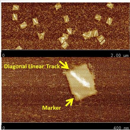
Regular Rectangular OrigamiWe started by trying to form a regular rectangle to make sure our protocols worked as expected. 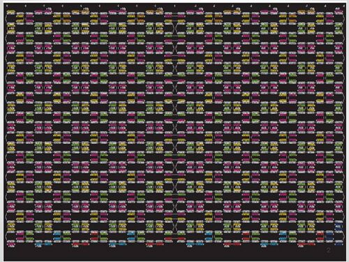 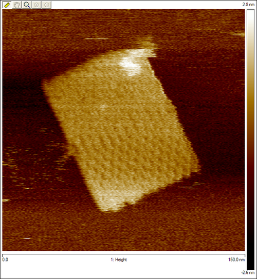 Origami with ProbesWe reformed the regular rectangle using our modified staple strands (at the locations we would put the tracks in Figure 1) to show that the probes don't interfere with the binding in the rectangle. 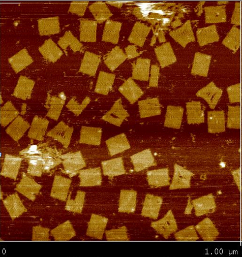 Origami with TracksDiagonal tracks were well formed on the origami as shown in the figure.
Origami with Unobservable WalkerWe attempted to insert our walker at the beginning of the track for the first time, but we can't see it on the AFM images. This could be due to any one of a number of issues as discussed above. 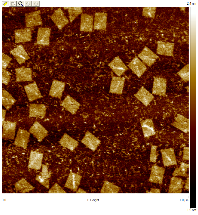 Origami with Streptavidin ControlWe first see what our walker should look like by adding another control to our origami. The new bright dot is the biotinylated control staple (green dot in Figure 1) bound to streptavidin, which is tested by a biotinylated staple as discussed above. 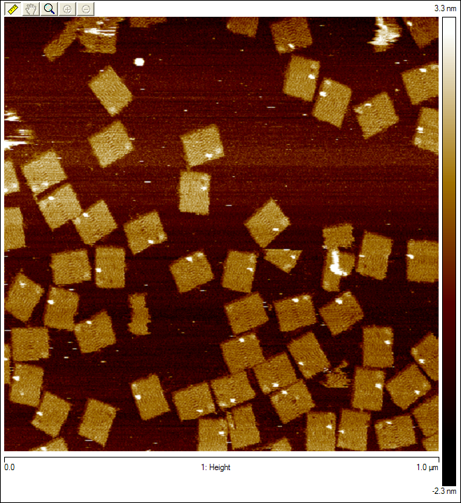 Origami with Observable Annealed WalkersSuccessful images showing that walkers are landing on the surface. Consecutive images of origami with no probes, except for the one the walker is attached to. Blue circles indicate origami with potential visible walkers. Red circle shows origami with a potential walker in the wrong position. 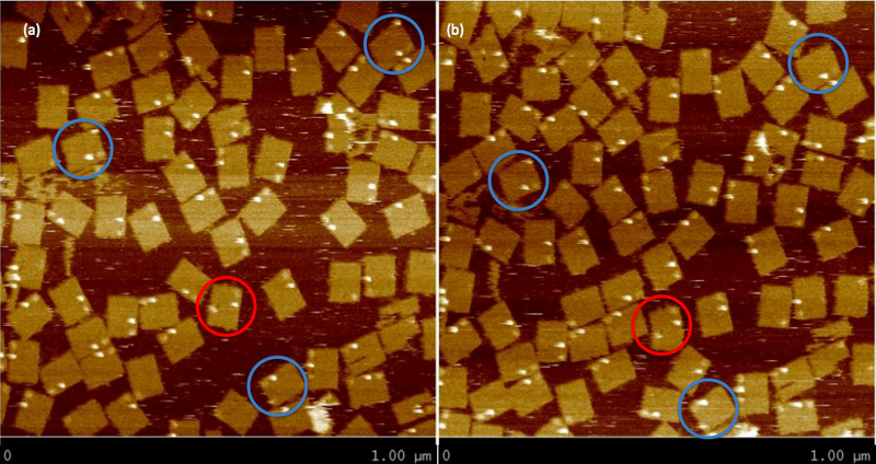 Origami with Observable Walkers on TracksSuccessful images showing that walkers are landing on the surface with tracks. Blue circles indicate tracks that we speculate have the walker at the starting position. Red circles indicate tracks that we speculate have the walker, but either at the wrong position or at multiple positions, perhaps due to some remaining free-floating streptavidin. 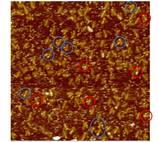 Walker Lock-Down ProtocolHere we provide a high level overview of the protocol we use to lock-down the walker in place. For a more detailed description of the protocol see protocol page. Essentially, we want to take advantage of the fact that up to four biotins can bind to a single streptavidin protein. Since there are tracks surrounding the walker (regardless of the walker's position), if we place biotinylated walkers on those surrounding tracks, they can bind to the same streptavidin as the original walker. Thus, we can form spiders [1] that are less likely to dodge the AFM tip since they are not as floppy. We can clearly add walkers such that they bind to every track in solution to achieve this, but since there is excess streptavidin in solution, all walkers that land on origami can form spiders with their neighbors, which means we should expect the entire track to be bright, rather than just the position of the original walker. Thus, before adding the extra biotinylated walkers, we must first wash the buffer on the mica to remove all excess streptavidin, so the only spiders that form are those involving the original walkers. This protocol proved to be successful using 3'-end biotinylated walkers, but so far has not worked using 5'-end biotinylated walkers. References
|

