BME100 f2017:Group14 W0800 L6
Our Company: Stand Graphics
 |
 |
 |
 |
 |
Bayesian Statistics
Overview of the Original Diagnosis System
For our section of the lab, 17 different groups of about 5-6 students per group each tested 2 patients, resulting in a total of 34 diagnosed patients. The patients were tested for a single nucleotide polymorphism (SNP) present in their DNA that is related to Alzheimer’s disease. Each team tested the positive control, negative control, patient 1, and patient 2 three times to minimize error by providing teams with multiple results for comparison. The program ImageJ was used to analyze the results and Bayesian statistics were implemented to determine if the results were in fact reliable. The same settings were used for each photo in ImageJ to also minimize errors. Two people conducted the PCR lab the first week and the Fluorimeter lab the second week. While the two were conducting the labs, the remaining group members worked on gathering data, calculating results, and analyzing the photos of the drops through ImageJ. The data from each group in our lab section was then congregated on a shared document so we could then analyze how reliable the tests were. Unfortunately, a couple groups yielded inconclusive results and one of the groups did not yield any data from their trials at all.
Formula: P(A|B) = P(B|A) *P(A) / P(B)
Sensitivity: the ability of a test to correctly identify those with the disease (positive)
Specitivity: the ability of the test to correctly identify those without the disease (negative)
Probability a patient will have a positive final test conclusion given a positive PCR reaction:
| Variable | Description | Numerical Value |
|---|---|---|
| A | Frequency of disease-positive conclusions | 0.25 |
| B | Frequency of positive PCR reactions | 0.274 |
| P(B/A) | Frequency of positive PCR reactions, given a disease-positive conclusion | 0.870 |
| P(A/B) | Frequency of a disease-positive test conclusion, given a positive PCR reaction | 0.794 |
Probability a patient will have a negative final test conclusion given negative diagnostic signal:
| Variable | Description | Numerical Value |
|---|---|---|
| A | Frequency of disease-negative conclusions | 0.679 |
| B | Frequency of negative PCR reactions | 0.631 |
| P(B/A) | Frequency of negative PCR reactions, given a disease-negative conclusion | 0.906 |
| P(A/B) | Frequency of a disease-negative test conclusion, given a negative PCR reaction | 0.975 |
Probability a patient will develop the disease given a positive final test conclusion:
| Variable | Description | Numerical Value |
|---|---|---|
| A | Frequency of a "yes" diagnosis | 0.286 |
| B | Frequency of a positive final test conclusion | 0.25 |
| P(B/A) | Frequency of a positive PCR result given a "yes" diagnosis | 0.571 |
| P(A/B) | Frequency of a "yes" diagnosis given a positive PCR result | 0.653 |
Probability a patient will not develop the disease given a negative final test conclusion:
| Variable | Description | Numerical Value |
|---|---|---|
| A | Frequency of a "no" diagnosis | 0.786 |
| B | Frequency of a negative final test conclusion | 0.679 |
| P(B/A) | Frequency of a negative PCR result given a "no" diagnosis | 0.842 |
| P(A/B) | Frequency of a "no" diagnosis given a negative PCR result | 0.975 |
What calculation describes the sensitivity of the system regarding the ability to detect the disease SNP? Calculation 1, 0.794
What calculation describes the sensitivity of the system regarding the ability to predict the disease? Calculation 3, 0.653
Which calculation describes the specificity of the system regarding he ability to detect the disease SNP? Calculation 2, 0.975
Which calculation describes the specificity of the system regarding the ability to predict the disease? Calculation 4, 0.975
Sources of Error
There are multiple sources of error that could have affected our results. First and foremost, the results relied on the photos captured by a camera. The groups used their phones to capture the photos, and each had a different camera quality which could skew the results. Additionally, the distance of the camera varied across groups and some groups even changed the distance each time they captured a photo, yielding inconsistent results. The lighting could have also been a source of error because sometimes the lid of the box was not completely shut, meaning the fluorescence captured of the drops may have been inconsistent. Lastly, there could be errors in the calculations obtained if ImageJ analysis was done improperly. ImageJ is a very complex system, so it would have been easy to make a simple mistake in tracing the drop during use of the program.
Computer-Aided Design
Fluorimeter System
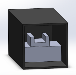
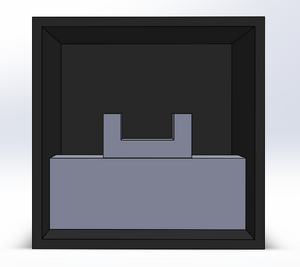
The fluorimeter setup within the light box will remain the same as provided in the previous lab. The fluorimeter itself requires the mixture of a dye and the solution that is being measured for DNA concentration. A drop of this mixture is placed on a glass slide and is illuminated by a blue LED within the light box. Using a smartphone, a picture is taken from which the intensity of the light can be determined and consequently, the concentration of DNA. The fluorimeter is set up within a box to keep most external light out, but leaves an opening to allow pictures to be taken without interference.
3D Representation of Fluorimeter
Our Design: Simplifluorimeter
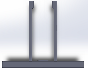
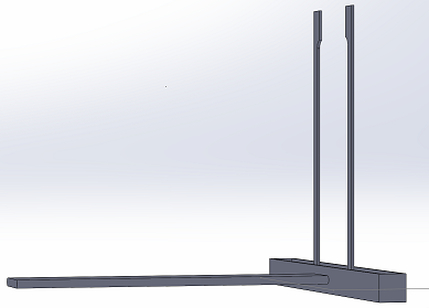
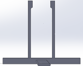
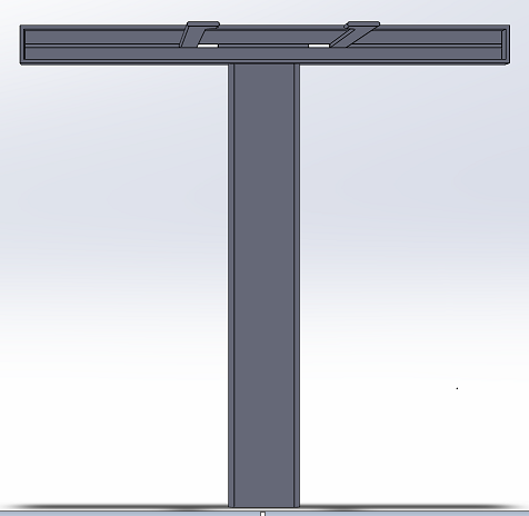
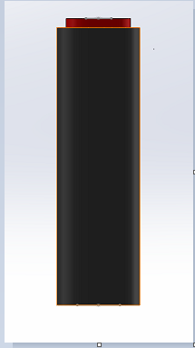
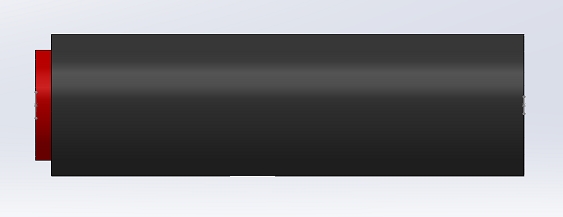
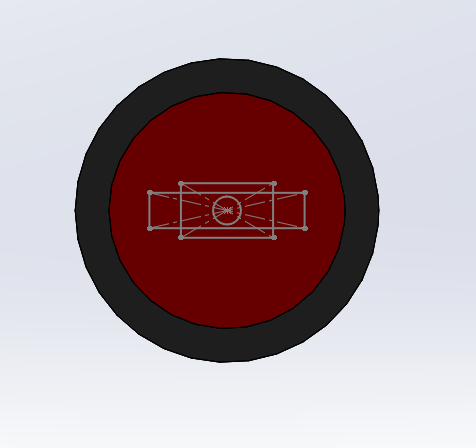
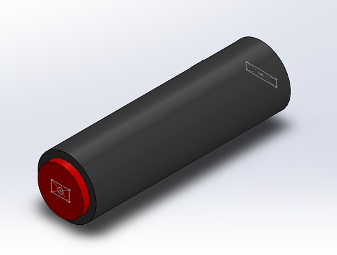
We went for a straightforward, yet effective and intuitive design that simplifies the picture taking process in the Fluorimeter system. The new and improved stand now accommodates for a wide variety of smartphones, with sizes compatible with Apple's iPhone 7 Plus, and Samsung's Galaxy Note 8. With the addition of an adjustable frame on the stand, one's phone can be secured on the stand while being able to manipulate the center frame of the phones camera. This feature along with the retractable "leg" of the stand, allows for users to reduce variability in the photo taking process by being able to set the stand at a fixed distance from the Fluorimeter apparatus (the drop on the slide). Lastly, through the use of the bluetooth camera button, users will be able to trigger the capture of an image(s) (whether it's commencing a timer, or taking single shots) after connecting their smartphone to the bluetooth connection on the switch. This feature can prevent the entrance of light from the lightbox, by allowing to the user to leave the lightbox completely sealed while taking photos.
3D Representation of Stand
3D Representation of Bluetooth Camera Switch
Feature 1: Consumables
Our PCR kit will include the same consumables that are typically required in order to perform a PCR reaction. These consumables include: a micropipette, micropipette tips, plastic-colored PCR test tubes, glass slides, PCR mix, a primer solution, a buffer solution, an indicator enzyme (like SYBR Green solution), as well as latex protective gloves. The aforementioned consumables are vital to PCR analyzation and each plays an important role in the process. Including these consumables in our PCR kit will help reduce waste of certain consumables as well as eliminate the need to look else where for such necessary items. Each consumable will be well packaged for maximum protection and elimination of contamination which can potentially skew data. Additionally, each of the consumables will be prepared and ready for use as soon as the PCR kit is delivered. The glass slides will fit the standard fluorimeter and the PCR test tubes will fit in any typical PCR machine. All the consumables will be appropriately labeled to avoid any consumer confusion, and a brief instruction manual will be included to explain each of the consumables and their functions to help reduce human error.
Feature 2: Hardware
We used the same PCR machine design that was given in the lab. The flaws in the PCR machine was not significant enough to effect cost, accuracy or usability.
Our major system changes were within the fluorimeter. Our fluorimeter has a more stable and adjustable stand. The stand will be in a constant place and be attached to the flourimeter box. It also includes a bluetooth button that will take the photos so that someone doesn’t have to let light in with sneaking their finger into the box. These changes were made so the pictures would be more accurate and have less random differences between them that are unrelated to the actual differences in the sample.
New step by step:
1. Place a 160 microliter drop of water (H2O) in the middle of the first two rows of the slide using the pipettor so that the drop is pinned and looks like a beach ball.
2. Turn on the excitation light using the switch for the Blue LED.
3. Turn on the camera of your smart phone and check the settings on the smartphone (if they can be adjusted) as described in steps A – F above.
4. Place your smart phone on the cradle at a right angle from the slide. No adjustment is required as the new stand has a constant unmoving setting.
5. Make sure the bluetooth button is synced to the cell phone so it will take pictures when it is pressed.
6. Close the box, take the pictures of the drop and repeat as often as necessary for all samples.
