3D printing - Mitchell Culler, Helen Hua, Elizabeth Lin
3D Printing
Woodblock printing is the first printing technology developed, dating circa 200[4]. As time goes on, more advanced technologies were introduced. In 1983, the first 3D printer was invented by Chuck Hall[4].
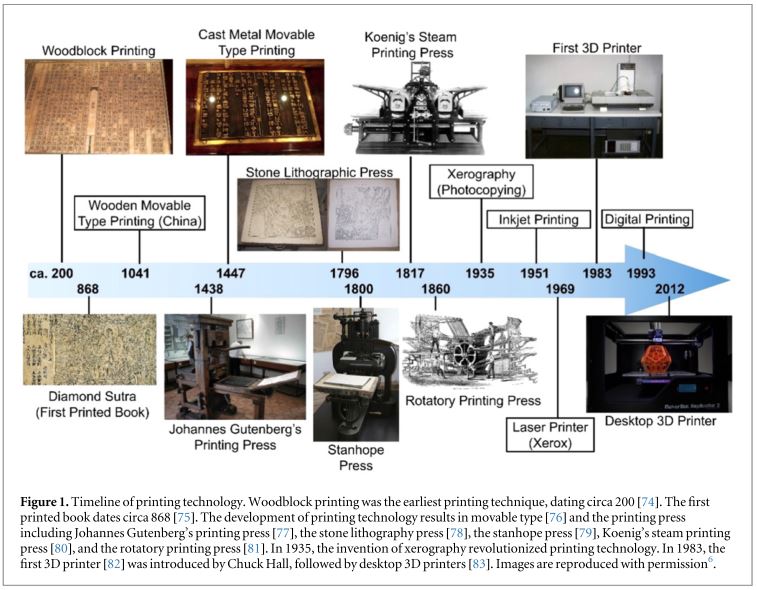
3D printing is also called the additive manufacturing. It is the process of creating a three-dimensional object from a digital file based on layer-by-layer deposition[1]. Each layer can be seen as a cross-sectional view of the object. To 3D print an object, a model needs to be created by Computer Aided Design (CAD) software.
Unlike any computer numerical control (CNC) machining, 3D printing can produce a more complex structure with less material used.
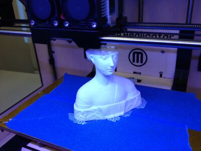
Types of Printing
There are many different technologies to do 3D printing. Since 2010, the American Society for Testing and Materials (ASTM) carried out the “ASTM F42 – Additive Manufacturing” standards[2]. Those standards are used to classify the additive manufacturing processes into 7 categories[2].
Those 7 categories are[2] [6]:
- Vat Photopolymerisation
- Stereolithography (SLA)
- Digital Light Processing (DLP)
- Continuous Liquid Interface Production (CLIP)
- Material Jetting
- Binder Jetting
- Material Extrusion
- Fused Deposition Modeling (FDM)
- Fused Filament Fabrication (FFF)
- Contour Crafting
- Powder Bed Fusion
- Selective Laser Sintering (SLS)
- Direct Metal Laser Sintering (DMLS)
- Sheet Lamination
- Directed Energy Deposition
Stereolithography
Stereolithography (SLA) is one of the most widely used 3D printing techniques[3], it is categorized into the vat photopolymerisation group by ASTM[2]. SLA printing technology was first introduced in 1983 by Chuck Hull[4].
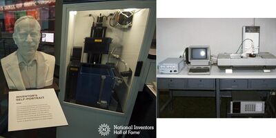
This technique involves using a vat of liquid resin and a positionally programmed laser[3]. Basically, the liquid resin is placed in a reservoir, the programmed laser scans over the resin surface to initiate photo-polymerization[3]. During the liquid resin photo-curing process, the resin is cured from liquid to solid through a chemical cross linking process[3]. The SLA 3D printing process is shown in the figure below.
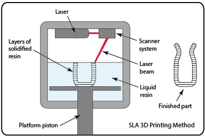
Although the SLA 3D printing method is used widely in different fields, such as printing living tissues, food; two problems will appear when using the SLA method, processing time and thermo-mechanical strength and stability[3]. There are studies shown that by incorporating more nanocomposite material, such as replacing the material using plant-based resins, can improve the thermo-mechanical performance, even stimuli-responsive properties[3].
3D Printing Techniques
In recent years, 3D printing has become much more accessible and affordable as a way to generate complex prototypes very rapidly compared to conventional manufacturing methods. As 3D printing becomes more “mainstream,” both as a concept and a practice, the technologies available for usage become myriad. While 3D extrusion printing has gained a significant following with consumers, there are many other types of additive manufacturing processes that are available and can be tailored to a wide range of applications.
Fused Deposition (Extrusion) Printing
This is the most common and most mainstream 3D printing method. Consumer-level 3D extrusion printers are available very inexpensively, with many options in the range of a few hundred dollars. This method allows for myriad materials to be used. Theoretically, any material that be melted and cooled to a solid can be used with extrusion 3D printing. One drawback of this method as it applies to microfluidics is that the resolution of these extrusion printers is typically not low enough to be effective for microfluidics channels, although recent improvements have placed resolution down to the micrometer scale[7]. Additionally, during printing in this method, it is very difficult to get the layers to line up perfectly, making it difficult to use this method to contain fluids.

In order to compensate for this drawback, there are several options available for finishing 3D models made using this technique such as exposing the model to a higher temperature so as to re-melt the layers together for a better fit, or using an appropriate chemical gas to partially dissolve the exposed outer layers and smooth them together. Current “affordable” 3D printers can achieve resolutions around 50 microns[12].
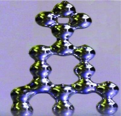
An example technique which has potential to make this method more specific to microfluidic structures is described by Ladd et al. [8]. This research is particularly interesting because this printing occurs at room temperature. A gallium and indium ally with an oxide over layer was able to be extruded through a needle to achieve a resolution of approximately 8 mm. The researchers were able to create wires, arrays of spheres, arches and interconnects.
Selective Laser Melting/Sintering
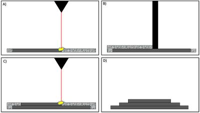
In contrast to extrusion printing where the printed material is extruded from a moving tip, this method involves using a bed of a powdered material and fusing together a layer of that material in a specific shape using a laser. After adding another layer of the powder, it can then be fused on top of the previous layer, almost like a reverse CNC milling process in that an object is constructed by fusing powder together instead of shaving material off a starting block. Although this allows for a very high resolution, one drawback to this approach is that the powder must be removed after the manufacturing process. For the scale of the small capillaries that microfluidics research necessitates, this makes this method somewhat unsuited to microfluidics channels [9]. Using CO2 laser machining of polymethyl methacrylate (PMMA) Romoli et al. were able to adopt the technique to create 3D structures by printing several PMMA sheets and then bonding them together [10].
Ink-Jet Printing
Due to the extremely low cost and availability of ink jet printers, this technique promises to be extremely useful for developing low cost microfluidics solutions. When used in two dimensions, this method typically involves printing hydrophobic boundaries which might be made from wax or polymer onto hydrophilic paper. A recent publication [11] described a technique wherein this method can be used for 3D printing using two different polymer inks. The first is made from SU-8, which forms the channels, while PMMA supports the structure during the curing process but is subsequently removed by washing. A relatively high vertical resolution of 4.6 um has been reported using this method [11]. The manufacturing steps involve printing an isolation layer. On top is printed a support material using PMMA. The microfluidics channel is then printed on top of the support material, and finally the support material is washed away.
Materials
3D Printing of Polydimethylsiloxane
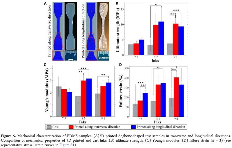
3D printing technique is widely used to print polydimethylsiloxane (PDMS) based microfluidic devices. 3D rapid prototyping fabrication technique maintains the desirable permeability and bio-compatibility of PDMS[5]. The ink for 3D printing PDMS can be prepared by blending a shear thinning PDMS material, and a low-viscosity PDMS material[5]. After desired mixing, the final PDMS inks were loaded into a syringe barrel at room temperature[5]. Using a 3D bioprinter, different nozzle pressures, extrusion pressures, and printing speed can be controlled[5].
Using this 3D printing technique, the PDMS object has a higher mechanical properties due to decreased porosity and bubble entrapment[5].
3D Printing of Polylactic Acid
Polylactic acid (PLA) is one of the most commonly used plastics for 3D printing. It is a biodegradable polymer which is produced from the bacterial fermentation of plants such as corn, potato, or cassava. It is approved by the USDA for food contact, which means that it is potentially food safe [13]. In reality, there are other aspects inherent to the 3D printing process, such as the metal nozzle (which may or may not be food safe and could contain metal contaminants such as lead) or small crevices which are difficult to clean, which create complications for 3D printing with food products.
Total Volatile Organic Compound Emission During 3D Printing
Although 3D printing is a very popular technology to control and to produce high quality products, there is no control on the total volatile organic compound (TVOC) emissions[6]. The TVOC including benzene, ethyl-benzene, toluene, can induce eye and throat irritation, damage liver and central nervous system[6]. The environment will also be polluted. When using the SLA 3D printing method, a large amount of TVOC emission will be produced from the photosensitive liquid resins and the 3D printing activities[6].
Two strategies were proposed by Yang's group to reduce the TVOC emissions[6].
- Titanium Dioxide photo catalytic oxidation method[6]
- Activated Carbon absorption method[6]
By incorporating those two strategies into the SLA process, the average TVOC concentration is reduced 44.14% by the first method and 71.06% by the second method. 62.74% TVOC emission caused by printing activities are reduced by the first method, and 68.54% by the second method[6].
Applications
Microfluidic Robots
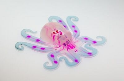
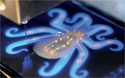
3D printed microfluidic robots are a recent advancement that combines microfluidic technology and soft robots to create fully soft, autonomous robots, such as the Octobot, shown in the figure below [14].
Soft Robots
Robotics is one of the most recent human advancements, made to carry out tasks for humans or imitate human tasks. Much of the structure of robots are inspired by nature, mimicking humans, spiders, and several other animals. Robots can be made with rigid bodies or soft bodies. Robots with rigid bodies are typically made to perform one task efficiently, but cannot adapt to different and new environments. The hard surfaces and rigid joints of the robots create an unsafe environment to interaction with humans [15].
Soft robots have properties that are difficult to achieve with rigid-bodied robots. The robots can be made from hydrogels, granular media, or elastomers. They are physically resilient, more flexible, and can potentially be able to passively adapt to environment [14]. An example of a soft robot is shown in Figure 2, a manta-ray inspired soft robot.
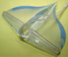
The technology of robots made of soft materials can produce robots that can adapt to natural environments. With current technology, soft robots are still connected to hard control systems. Producing fully autonomous soft robots presents a great challenge without incorporating rigid, hard systems. [14].[15]
Microfluidic Driven Actuation
In microfluidic devices, actuation can be done using pressure generation. To replace the use of electrical energy and its constraints, pressure generation is a convenient actuation source, creating a pneumatic battery . One approach to create pressure is through a chemical reaction. A chemical reaction that generates gas will increase the pressure within the system and can power the device. [15]
Octobot
The Octobot is a 3-D printed microfluidic robot that is fully autonomous. The robot is made completely of soft materials, such as polydimethylsiloxane (PDMS), Pluronic F127, and SE 1700 and Sylgard 184, which are silicone-based materials. The Octobot is powered by a microfluidic logic controller and a decomposition reaction that generates gas.[14]
Fabrication
Several different techniques are used to produce the Octobot. The body of soft lithography and micro-moulding and embedded 3-D (EMB3-D) printing. The printing process can be seen in the figure below.
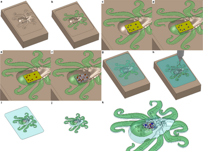
Micro-molding
The soft controller for the microfluidic logic is made using micro-molding. It is covered with a polyimide mask for protection and placed into a mold filled with hyperelastic layers for actuation. The mold is then filled with the body matrix materials and crosslinked.
EMB3-D Printing
The mesofluidic networks were created by combining micro-moulding and EMB3D printing. A fugative ink was used to pattern the networks, which can be shown in the figure above. The fuel reservoirs, reaction chambers, actuation networks, and vent orifics were all EMB3D printed using hydrogel-based inks,including fugitive and catalytic inks.The fugitive ink is composed of a triblock polymer gel and the catalytic ink contains platinum particles in a suspension with Pluronic 127. The properties of these inks were tailored for EMB3D printing [14] and can be changed by varying the print speed.
Actuation
The octobot is controlled fully through microfluidic logic, without the need of any hard, rigid control systems. A soft, microfluidic controller sits at the center of the Octobot. The controller regulates fluid flow and the catalytic decomposition of the monopropellant fuel inside the robot.
The microfludic controller is shown in the figure below.
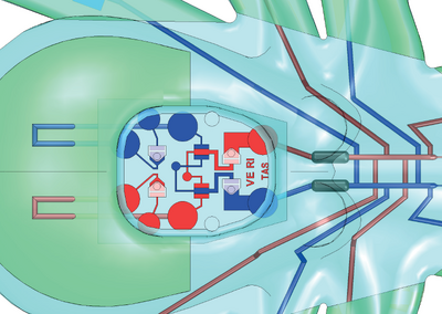
The controller system is divided into four sections: upstream for liquid fuel storage, oscillator for liquid fuel regulation, reaction chamber for the decomposition into pressurized gas, and downstream for gas distribution for actuation and venting.
In the upstream section, the fuel reservoirs are filled using a syringe pump. Backflow into the fuel inlets is prevented using check valves.
The networks downstream from the reaction are inflated from the gas produced from the fuel decomposition. The inflation causes parts of the Octobot to move.
The power source of the robot is the decomposition of aqueous hydrogen peroxide, shown in the reaction below.
2H2O2 (l) → 2H2O (l,g) + O2 (g).
The reaction results in a 240-fold volumetric expansion.
The controller is designed to operate at fuel flow rates of 40 μl min-1, with a fuel capacity of 1 ml, resulting in a theoretical run time of 12.5 minutes. [14]
-
Top-view of Octobot in motion (Image:Wehner,M. and et. al.,2016).
-
Front-view of Octobot in motion (Image:Wehner,M. and et. al.,2016).
Food Science and Nutrition
As the global population size increasing with time, providing sustainable nutrition and appealing food becomes an ongoing problem[1]. Since 3D printing technique can create desired and appealing 3D objects using various materials, this technique can serve as a new potential cooking way to feed all the global population[1]. For example, insects are highly nutritional, they are rich in proteins and healthy fats, but most people do not accept eating insects. Utilizing this 3D printing technique, more food materials can be used and provided to the public[1]. The appearance and texture of food product can be improved[1], more people can accept healthy but unappealing food. Food can be personalized by adding or reducing certain ingredients in the food "ink" for special treatment or extra care[1].
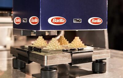
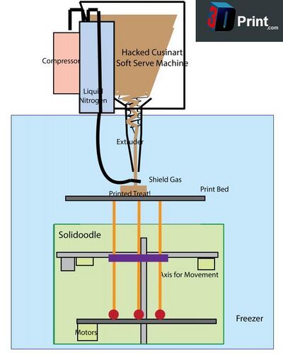
Fused Deposition Modeling (FDM) method is normally used for 3D printing food[1]. Molten materials in liquid state, such as sugar, chocolate, gelatin can be printed using this method[1]; Purees, gels, and doughs can be deposited directly without any structuring agent to support the structure[1]. The fundamental structure of a 3D food printer usually has an extruder which is a syringe that is connected to an electric engine at one end and few nozzles at the other end[1]. Ingredients are mixed and stored in reservoirs and containers, the nozzles deliver the ingredients, extruders are used to push different materials or color mixing by a colormix generator[1]. Materials are layered and deposited onto he heating platform, the platform can be also used to cook the row food[1].
References
- Yang F, Zhang M, Bhandari B. Recent development in 3D food printing. Crit Rev Food Sci Nutr 2017;57:3145–53. DOI:10.1080/10408398.2015.1094732
- What is 3D printing? 3DPrinting.com 2018.[7]
- Manapat JZ, Chen Q, Ye P et al. 3D Printing of Polymer Nanocomposites via Stereolithography. Macromol Mater Eng 2017;302:1–13. DOI:10.1002/mame.201600553
- Amin R, Knowlton S, Hart A et al. 3D-printed microfluidic devices. Biofabrication 2016;8, DOI:10.1088/1758-5090/8/2/022001.
- Ozbolat V, Dey M, Ayan B et al. 3D Printing of PDMS Improves Its Mechanical and Cell Adhesion Properties. ACS Biomater Sci Eng 2018:acsbiomaterials.7b00646. DOI:10.1021/acsbiomaterials.7b00646
- Yang Y, Li L. Total volatile organic compound emission evaluation and control for stereolithography additive manufacturing process. J Clean Prod 2018;170:1268–78. DOI:10.1016/j.jclepro.2017.09.193
- A. A. Yazdi, A. Popma, W. Wong, T. Nguyen, Y. Pan, and J. Xu, “3D printing: an emerging tool for novel microfluidics and lab-on-a-chip applications,” Microfluid. Nanofluidics, vol. 20, no. 3, p. 50, Mar. 2016. DOI: https://doi.org/10.1007/978-3-319-40036-5_4
- C. Ladd, J.-H. So, J. Muth, and M. D. Dickey, “3D Printing of Free Standing Liquid Metal Microstructures,” Adv. Mater., vol. 25, no. 36, pp. 5081–5085, Sep. 2013. DOI: https://doi.org/10.1002/adma.201301400
- P. H. King, “Towards rapid 3D direct manufacture of biomechanical microstructures,” 2009. EThOS:[[8]]
- L. Romoli, G. Tantussi, and G. Dini, “Experimental approach to the laser machining of PMMA substrates for the fabrication of microfluidic devices,” Opt. Lasers Eng., vol. 49, no. 3, pp. 419–427, Mar. 2011. DOI: https://doi.org/10.1016/j.optlaseng.2010.11.013
- W. Su, B. S. Cook, Y. Fang, and M. M. Tentzeris, “Fully inkjet-printed microfluidics: a solution to low-cost rapid three-dimensional microfluidics fabrication with numerous electrical and sensing applications,” Sci. Rep., vol. 6, no. 1, p. 35111, Dec. 2016. DOI: 10.1038/srep35111
- G. Comina, A. Suska, and D. Filippini, “Low cost lab-on-a-chip prototyping with a consumer grade 3D printer” Lab on a Chip, 2014,14, 2978-2982. DOI: 10.1039/C4LC00394B
- R. Auras, “Poly(lactic acid,” 2010, John Wiley & Sons, Inc. DOI: https://doi.org/10.1002/0471440264.pst275
- Wehner, M.; Truby, R. L.; Fitzgerald, D. J.; Mosadegh, B.; Whitesides, G. M.; Lewis, J. A.; Wood, R. An integrated design and fabrication strategy for entirely soft, autonomous robots J. Nature. 2016, 536 (7617), 451–455. DOI:10.1038/nature19100
- Rus, D.; Tolley, M. T. Design, fabrication and control of soft robots. Nature 2015, 521 (7553), 467–475. DOI:10.1038/nature14543
- Onal, C. D., Chen, X., Whitesides, G. M. & Rus, D. Soft mobile robots with on-board chemical pressure generation. In 15th International Symposium on Robotics Research (ISRR 2011) 1–16 (2011). [[9]]
