20.309:Homeworks/Homework1
Question 1:Wheatstone Bridge
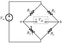
Figure 1 shows a resistor network known as a Wheatstone bridge. This is a common circuit used to measure an unknown resistance. Rx is the component being measured, and R3 is a variable resistor (often called a potentiometer or just a pot for no sensible reason).

(a) The bridge is balanced when Vab is zero. Assuming R3 is set so the bridge is balanced, derive an expression for Rx in terms of R1, R2 and R3.
(b) Now let R3 also be a fixed resistor. Suppose that Rx varies in a way that makes Vab nonzero. Derive an expression for the current that would flow if you connected an ammeter from a to b. Assume the ammeter has zero internal resistance.
Question 2: Measuring Physical Quantities with a Wheatstone Bridge
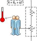
A thermistor is a resistor whose value varies with temperature. Thermistors are specified by a zero power resistance, R0, at a given temperature and a temperature coefficient, α. As shown in Figure 2, a small person inside the thermistor observes the temperature on a thermometer and adjusts a variable resistor so that R=R0+αT, where T is the temperature.

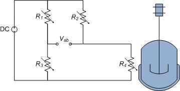
Now imagine a Wheatstone bridge made out of four identical thermistors, as shown in figure 3. One of the thermistors (R4) is attached to an odd-looking blue apparatus that varies in temperature. The other three are maintained at a constant 20°C.

(a) Derive an expression for Vab as a function of temperature.
(b) What if both R1 and R4 are attached to the apparatus? Which configuration is more sensitive to temperature variations?
Question 3: Photodiode I-V Characteristics
Using the data that you collected in the lab for the photodiode, generate 3-4 i-v curves for a photodiode at different light levels (including in darkness). Plot these on the same graph to see how incident light affects diode i-v characteristics.
Give a brief (qualitative) explanation for why photodiodes are best used in reverse bias?
Question 4: Unknown Transfer Functions
For the black boxes that you measured in the lab, determine what kind of circuit/filter each one is (two of them will look similar, but have an important difference - what is it?). Determine a transfer function that can model the circuit, and fit the model to the data to see whether the model makes sense.
Of the four boxes, "D" is required, and you should choose one of either "A" or "C". You can fit "B" for bonus credit.
Question 5:Power in a Voltage Divider
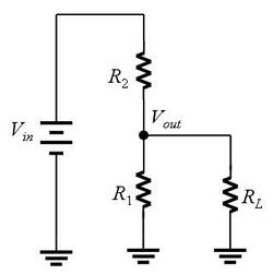
Referring to the circuit shown in Figure 4, what value of RL (in terms of R1 and R2) will result in the maximum power being dissipated in the load?
(Hint: this is much easier to do if you first remove the load, and calculate the equivalent Thevenin output resistance RT of the divider looking into the node labeled Vout. Then express RL for maximal power transfer in terms of RT.
