BioBuilding: Synthetic Biology for Students: Lab 3--Electronics For Splash
Part II. Electronic vs Biological Circuits

In this activity, we'll explore signaling in the context of an electrical circuit. As you work through this exercise, consider how the lessons learned from experimenting with an electronic circuit would map to the engineering of biological systems. You will be given a kit to construct this circuit.
Before you Begin
Safety:
In this exercise, you'll be working with circuits connected to a battery. Although you are unlikely to seriously injure yourself, you should make a habit of unplugging / powering-off the circuit before you touch it.
Terminology:
The two terminals of the battery are labeled with a plus (high voltage, red wire) and minus (low voltage, black wire). When building a circuit, these are also referred to as power and ground, e.g. "To apply voltage across a resistor, connect one end of the resistor to power and the other end to ground."
The letter omega (Ω) is the symbol for ohm, the unit of resistance. You will be using a small 820Ω resistor (marked with tape) and a large 10MΩ (10 mega-ohm / 10 million ohm) resistor in this exercise.
Safety for the circuit components:
- Never directly connect the two battery terminals with wire. This is called a "short circuit" and can damage or drain your battery.
- Take note of which components require voltage to be applied in one direction and not the other. Applying voltage backwards can fry your components. Specifically:
- The OpAmp has one pin devoted to power and one devoted to ground.
- The LED has two wires, a positive leg and a negative leg. The positive leg must be toward power, and the negative leg toward ground. To figure out which is which, feel the body of the LED. It is round, except for one flat side, which indicates the negative leg. (To remember this, think of the flat side as looking like a minus sign. The negative leg may also have a shorter wire, although this indication will be lost if the wires have been clipped.)
- The phototransistor is also directional, with a flat side. Which direction to plug it in depends on how it is being used.
- Wires and resistors don't care which direction they are plugged in.
Introduction to Breadboards
(If you have used a breadboard before, feel free to skip this section.)
You will be building this circuit on a breadboard. Breadboards allow us to connect, disconnect, and move around circuit components easily and cleanly. It's much easier to build on a breadboard than to just wire everything together.
...But how do those little holes connect the components together? Let's take a look at the back of a breadboard.
 |
 |
| Building on a breadboard. | The back of a breadboard, with the metal base removed and the backing peeled off. |
Each of these metal strips connects a group of holes. You can plug two wires into two holes in the same group, and those two wires will be electrically connected. The holes in the middle sections of the breadboard are grouped in short rows of five. The holes on the sides, however, are connected in long columns, forming rails that run all the way down each edge of the breadboard. Typically, one rail is connected to power and one to ground, conveniently delivering power and ground to the whole breadboard.
Lighting up an LED
Begin with a basic circuit, to familiarize yourself with the breadboard and the LED. Examine the circuit diagram below, and then replicate it on the breadboard. Use the small, 820Ω resistor for this (marked with tape).
 |
 |
| Circuit diagram. | Circuit as built on breadboard. |
Once you have gotten the LED to light up, disconnect everything.
A few points:
- If you don't see light, check the direction of the LED and the battery, and make sure all the wires that should be connected, are connected.
- The resistor is needed to limit the current (rate of flow of electrons) through the LED. Too much current can damage it. The LEDs in your kit are strong enough that they won't burn out right away if you connect them straight across the battery, but using a resistor is still a good idea.
- The path of current through the circuit you've built goes "power, LED, resistor, ground". You could change it to "power, resistor, LED, ground", and it would still work.
Playing with the Phototransistor
Next, observe the behavior of the phototransistor. A phototransistor acts like the reverse of an LED: where the LED takes an electric current and produces light, a phototransistor takes in photons and produces a current. The strength of the current depends on how much light is shining on the phototransistor. If you have a multimeter, you can observe this current.
- Set your multimeter to the 1mA (one milliamp) direct current setting. Make sure the multimeter probes are plugged in to the right sockets for measuring a direct current of this size.
- Connect the battery's red wire to the flat side of the phototransistor.
- Touch the red multimeter probe to the round side of the phototransistor. Touch the black probe to the battery's black wire.
- Shine a light on the phototransistor and watch the current reading change. Note the direction of current -- starting from the flat side and flowing out the round side.
Once you have observed the current changing, disconnect everything.
Tips on Using the OpAmp
Most components have long bendable wires attached to them. The OpAmp, however, is a complicated circuit in its own right, which has been packaged inside a little black box with short legs or "pins" on each side (an integrated circuit). To use the OpAmp, you must position it across the trench in the middle of the breadboard:

A few points:
- Notice how each pin is connected to its own individual row of holes. (If you plugged in the OpAmp in a different position, some of the pins would be connected to each other, and it would not work.)
- Notice the small circle/divot in the top / upper left corner of the chip, indicated by an arrow. It lets you know which way is up, and which pin is Pin 1. Pin 1 is always the top left pin.
- This picture is annotated with the triangular OpAmp symbol drawn on the back of the chip, showing which pins correspond to the OpAmp's plus input, minus input, and output (described further below). Two of the remaining pins are for power and ground. The others don't do anything, and are only included because the 8-pin package is a manufacturing standard.
What does an OpAmp do? OpAmp is short for "operational amplifier". Essentially, an OpAmp takes an input signal and amplifies it in various ways, depending on how other components are attached to it. OpAmps are very versatile devices. In our case, we will use a feedback resistor between the output and the minus input, which will make the OpAmp act as a current-to-voltage converter. Recall that the phototransistor produces only a very small current (a few milliamps) when light shines on it. The OpAmp's job is to convert that tiny current into a much larger voltage, which will drive the LED.
Analogy Between Electrical Circuit and Biological Circuit
Now that you've learned a bit about each component individually, you're ready to put them together. Just like the bacterial photography system, our circuit takes in light as input, translates the signal to a different form, and produces color as output. However, instead of signaling by the level of activity of various proteins, the signals in an electrical circuit are either voltage or current. When light hits the phototransistor, it generates a current signal. The OpAmp takes in this current signal and produces a voltage, which signals the LED to stop producing light -- so, just as in the bacterial photography system, the color output is the opposite of the light input.

Examine the circuit diagram above and consider the role played in it by each component:
- Phototransistor: a light sensor. When light shines on the phototransistor, current flows through it. The phototransistor is analogous to the Cph8-OmpR signaling system.
- OpAmp: a signal propagator. More generally, an OpAmp detects and amplifies a difference between the currents into its plus and minus inputs. In this circuit, the OpAmp compares the current from the phototransistor (minus input) to a zero current from ground (plus input). With the addition of the feedback resistor between the output and the minus input, the OpAmp converts a small current signal into a larger voltage signal. The OpAmp (plus feedback resistor) is analogous to the transcription/translation machinery in the cell, which translates an OmpR signal into synthesis of LacZ.
- Resistor: component which resists current flow, producing a difference in voltage between its two ends. The voltage difference equals the current times the resistance; thus, the value of the resistor sets the "gain" or amplification factor of the system. By varying the resistance, we can vary the circuit's sensitivity to light. The value of the gain resistor is analogous to the strength of the promoters and ribosome binding sites in the engineered LacZ gene, which raise or lower the efficiency of LacZ production, thus setting the overall sensitivity of the system.
- LED: a device with a detectable output. When voltage is applied across an LED, current flows through it and it emits colored light. The LED is analogous to LacZ. (The small 820Ω resistor's job is only to limit the current through the LED; it has no direct counterpart in the bacterial photography system.)
 |
 |
 |
 |
| Phototransistor (sensor) | OpAmp (signal conversion) | Resistor (gain) | LED (output) |
Building the Bacterial Photography Circuit
|
 |
| Circuit schematic. | Photo of finished circuit. |
Follow these directions to build the circuit, referring to the schematic and the photo as needed (a large color print is included at the back of this packet). A few notes have been added to the photo, to help you avoid placing components backwards. You need not make your circuit exactly the same way as shown in the photo; all that matters is that the connections are correct.
- Power the breadboard: Connect each battery lead to one of the rails on the sides of the breadboard. Note: in the photo, power is delivered to one of the rails on the right side of the breadboard, and ground to the left. (Before you continue building, power off the breadboard by disconnecting one of the rails or snapping the battery out of its holder.)
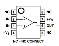
Pin connections of OpAmp chip. - Position the OpAmp across the trench in the breadboard, with the small circle/divot at the top.
- Refer to the connection diagram at right to see which pin is which. Power the OpAmp by connecting pin 7 to power and pin 4 to ground.
- Connect the OpAmp's plus input (pin 3) to ground.
- Add the phototransistor. Connect its positive leg (round side) to the OpAmp's minus input (pin 2), and connect its negative leg (flat side) to ground.
- Add the LED. Connect its positive leg (round side) to power, and its negative leg (flat side) to a free space near the OpAmp. Next, add the small 820Ω resistor between the LED's negative leg and the OpAmp's output (pin 6).
- Add the feedback resistor (the large 10MΩ one). Connect one of its wires to the OpAmp's output (pin 6), and the other wire to the OpAmp's minus input (pin 2).
- Double check your connections with the circuit diagram above before you power it up.
- Test your circuit by shining a light on the phototransistor and seeing if the LED responds. Remember, the LED should be ON when there is NO LIGHT on the photodiode, and turn OFF when there is LIGHT. If it doesn't, check the direction of your components, and make sure that the wires that should be connected are really connected.

Putting it all together
Think over the following questions and discuss them with your neighbors.
- Explain the role each component plays in the electronic circuit. Which part of the biological circuit does each represent?
- No doubt, building this circuit was quicker and easier than actually assembling a biological circuit -- for example, you didn't have to wait for bacteria to grow, or spend time cutting and pasting wires the way you would cut and paste DNA to make a functional plasmid. What are some traits of these components, of the breadboard, or of electronics in general, that make electrical engineering easy in this way?
- Every analogy has limitations. What are the limitations of the circuit you built as a model of the bacterial photography system? Could you do anything to make it more realistic?
Examining system behavior at different gain values
A circuit with very tight fully-on-or-fully-off behavior is more "digital", or switch-like, while a circuit with a wide middle range of response is more "analog", or dial-like. The range of flashlight intensities that can hold the LED half-lit is a measure of the gain or strength of the amplifier. More precisely, the gain is the slope of the LED-output-vs.-phototransistor-input line. Because the LED has a particular maximum brightness, a high-gain amplifier with a steep slope will quickly go from zero to maximum, whereas a low-gain amplifier will cause the LED's brightness to increase more slowly before maxing out. We can tune this gain by changing the value of the gain resistor.
Initial Condition: Resistance = 10 MΩ
Right now, the OpAmp's output and minus input are connected with a 10 MΩ resistor.
- What happens to the LED when you power up the circuit?
- What happens to the LED when you shine the flashlight on the phototransistor?
- Can you get the LED to hold steady at 1/2 its maximal brightness, by moving the flashlight farther away, shading it, etc?
- Sketch a graph with flashlight intensity on the x-axis and LED light intensity on the y-axis. With a 10 MΩ resistance in place, is the circuit's behavior better described as a switch, a dial, or neither (if it doesn't work at all)?
Modification: Resistance = 0Ω
Replace the 10MΩ resistor with a wire.
- What happens to the LED when you power up the circuit?
- What happens to the LED when you shine the flashlight on the phototransistor?
- Can you get the LED to hold steady at 1/2 its maximal brightness?
- Add a line for this circuit to your graph. Is this circuit's behavior better described as a switch, a dial, or neither?
Alternative: Resistance = infinite Ω
Remove the wire connecting the OpAmp's output to its negative input.
- What happens to the LED when you power up the circuit?
- What happens to the LED when you shine the flashlight on the phototransistor?
- Can you get the LED to hold steady at 1/2 its maximal brightness?
- Add one last line to your graph. Is this circuit's behavior better described as a switch, a dial, or neither?
Putting it all together
Think over the following questions and discuss them with your neighbors.
- Based on the real-life bacterial photos you have seen, is the real system more switch-like or dial-like?
- What are some everyday examples of switch-like and dial-like systems? What element or aspect plays the role of "gain" in each one? Can you think of examples from biology or medicine, as well as examples of electrical or mechanical machines?
- When might you want switch-like behavior in a biological system, and when might you want dial-like behavior?
