Peristaltic Pumps - Sarah Duquette
Introduction

Peristaltic pumps are a type of pump that works by displacing fluid using the process of peristalsis. During this process, fluid is pushed down a malleable tube by contractions of the tube walls. This process occurs in organs in the body such as the intestines and esophagus. Peristaltic pumps use this same principle of positive displacement to move fluids along a passage. These pumps use flexible tubing and rollers to compress the passage[1].
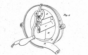
The peristaltic pump was first patented in 1855 by Rufus Porter and J. Bradley. At the time, they termed it the elastic-tube pump. Their device used compression to create a vacuum that would suck liquid along the passage. The tube exists in at least one coil or an arc so that rollers can compress the tube in two places at the same time. Their original design is pictured in Figure 1. This is the coil design where the tube is coiled around itself so that the roller can compress both tubes at once[2].
Design

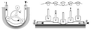
There are two basic designs of the pump, the linear design and the rotary design as seen in Figure 2. In both designs an elastic tube is compressed and this motion causes fluid to flow down a passage. Although the two designs look different, they both use the same principles to displace fluid and induce flow. Both systems allow for sterile movement of fluid. In the linear design of the peristaltic pump, a series of actuators rhythmically compress the elastic tube. The amount of actuator can be adjusted for the specific purpose of the pump. In the rotary design of the peristaltic pump, revolving rollers create a compressed section in the flexible tube. The amount of rollers and tube diameter can vary[1].
Peristaltic Pumps on the Microscale

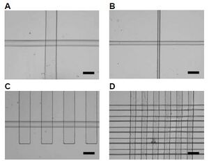
Alternatively, monolithic elastomeric valves and pumps can be fabricated using soft lithography for use on the microscale. An example of a elastomeric peristaltic pump can be seen to the right in Figure 3. Devices like this one, and other microfluidic devices, avoid several problems of alternative devices like the formation of bubbles and being dependent on flow. This design was arranged to have a crossed channel layout. The device works by pressure being applied to the upper channel which then causes the lower channel to close. This pushes the fluid along the pathway just like a peristaltic pump would. The fluid can remains sterile as it never needs to exit the tube or be exposed to outside contamination. The response time is extremely quick and the devices can be packed very close to each other. These pneumatic valves and pumps are useful for a large variety of applications, one of them being lab-on-a-chip[3].
Applications
Microfluidics
Peristaltic pumps can be widely used in microfluidics. One reason is because of the ease at which they can be made with PDMS and the wide variety of applications[1]. The reason peristaltic pumps are typically chosen over other types of pumps for microfluidic devices is because syringe pumps can be too bulky or not as easily portable as microfluidic systems are, electrokinetic pumps require lots of energy input, and acoustic pumps are limited to a low flow rate[4].
The device is designed to have a fluid channel in between the glass base and a very thin lay of PDMS. Above the thin layer of PDMS is a thicker layer of PDMS with an actuator channel which is at a right angle compared to the fluid channel. External pressure is applied to the actuator channel causing it to inflate. PDMS is elastic and can shift with this pressure fluctuation so it essentially closes and opens the fluid channel[1].
One example of a specific microfluidic peristaltic pump is a design relying on cam actuated compression. A series of cams rotate to compress the channel in a sequence. A motor drives the cam which is attached to the follower which moves straight up and down to compress the channel[4].
Microchip

With the development of microfluidic chips for lab on a chip or micro total analysis system applications, highly accurate methods of fluid delivery need to be utilized. These chips often require precise amounts of reagents to be added and for the fluids to move into and within the chip. Typical methods for this include syringe pumps and small gear pumps. However peristaltic pumps can also be used for this purpose as they are precise and also cost efficient. In particular, using linear peristaltic pumps can resolve many of the issues caused by other pumps methods and even circular peristaltic pumps[5].
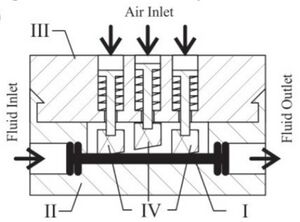
The design of the linear peristaltic pump to be used in combination with microfluidic chips is pictured in Figure 3. The actuators pinch the tube in a specific order and this causes a specific amount of the fluid to move from the inlet to the outlet. The tube is always closed as at least one actuator is shut to prevent the fluid from flowing backwards. This method is the same way fluid is moved down the esophagus, the difference being that muscles are the actuators. This system is held within a cartridge. The cartridge is made from PMMA[5].
These microchip devices that may rely on peristaltic pumps have many uses. For medical or chemical engineering applications, lab-on-a-chip or micro Total Analysis Systems are used to analyze samples. These systems can be used to scale down and study complex processes that require mixing, separating, and the adding of reagents. For example, these systems can be used to analyze small blood samples that need quick and accurate analysis. The peristaltic pump is useful with this system because fluid motion through the chip is necessary[5].
Blood Transfusions
In 1881, Eugene Allen designed a new device for blood transfusions which utilized the peristaltic pump. During this time period, blood transfusions were extremely dangerous and not very successful. This was due to the introduction of air and also blood clumps into the blood stream. The original device was composed of an elastic tube, where a roller was used to apply pressure at certain points to move blood through the tube. The idea is that this allows for flow of blood without any suction-valves which is what causes clots[6].
This device was modified and further developed by Michael Debakey. His design was more circular with a roller that can pinch to device in two spots for continuous motion[7].
Bioreactor Perfusion
Another area of new technology that uses peristaltic pumps is perfusion bioreactors. These reactors are particularly useful in tissue engineering. They are used to flush culture media across an engineered scaffold. The advantages are that shear stress can be applied to cells within the scaffold as well as the mass transport rate can be increased. Challenges can come up when working with different tissues, it can be expensive, and perfusion bioreactors can have lower growth rate. These perfusion bioreactors are typically designed to have a peristaltic pump. These systems are important and seem to be the future of tissue engineering[8]. The bioreactor environment is important for production of engineered tissues and organs. Specifically, perfusion bioreactors can be used to produce blood vessels and heart valves[9].
Perfusion bioreactors can also be used for continuous cell culture. Continuous cell culture is made possible by the continuous filtration of old media and replacing it with new nutrient filled media while leaving the cells to grow in the bioreactor. A way to continuously pump the media is using a peristaltic pump[10].
References
1. Berg, J. M.; Dallas, T. Peristaltic Pumps. In Encyclopedia of Microfluidics and Nanofluidics; Li, D., Ed.; Springer US: Boston, MA, 2008; pp 1626–1633. https://doi.org/10.1007/978-0-387-48998-8_1198 (accessed Fen 27, 2022).
2. Porter, R.; Bradley, J.D., Elastic-tube pump. U.S. Patent 12,753, April 17, 1855. https://patents.google.com/patent/US12753A/en (accessed Fen 27, 2022).
3. Unger, M. A.; Chou, H.-P.; Thorsen, T.; Scherer, A.; Quake, S. R. Monolithic Microfabricated Valves and Pumps by Multilayer Soft Lithography. Science 2000, 288 (5463), 113–116. https://doi.org/10.1126/science.288.5463.113 (accessed Fen 27, 2022).
4. Xiang, J.; Cai, Z.; Zhang, Y.; Wang, W. A Micro-Cam Actuated Linear Peristaltic Pump For Microfluidic Applications. Sensors and Actuators A: Physical 2016, 251. https://doi.org/10.1016/j.sna.2016.09.008 (accessed Fen 27, 2022).
5. Loth, A.; Forster, R. Pneumatic Actuated Linear Peristaltic Micro Pump for Standalone and On-Chip Applications. 2018 IEEE 13th Annual International Conference on Nano/Micro Engineered and Molecular Systems (NEMS) 2018. https://doi.org/10.1109/NEMS.2018.8557027 (accessed Fen 27, 2022).
6. Allen, E.E., Instrument for transfusion of blood. U.S. Patent 249,285, Nov 11, 1881, https://patents.google.com/patent/US249285A/en (accessed Fen 27, 2022).
7. Debakey, M.E. A Simple Continuous Flow Blood Infusion Instrument. New Orleans Med Surg J 1934, 87, 386. https://ci.nii.ac.jp/naid/10015127803/ (accessed Fen 27, 2022).
8. Dahlin, R. L.; Meretoja, V. V.; Ni, M.; Kasper, F. K.; Mikos, A. G. Design of a High-Throughput Flow Perfusion Bioreactor System for Tissue Engineering. Tissue Eng Part C Methods 2012, 18 (10), 817–820. https://doi.org/10.1089/ten.TEC.2012.0037 (accessed Fen 27, 2022).
9. Mironov, V.; Kasyanov, V. A.; Yost, M. J.; Visconti, R.; Twal, W.; Trusk, T.; Wen, X.; Ozolanta, I.; Kadishs, A.; Prestwich, G. D.; Terracio, L.; Markwald, R. R. Cardiovascular Tissue Engineering I. Perfusion Bioreactors: A Review. J Long Term Eff Med Implants 2006, 16 (2), 111–130. https://doi.org/10.1615/jlongtermeffmedimplants.v16.i2.10 (accessed Fen 27, 2022).
10. Going from Fed-Batch to Perfusion. http://www.biopharminternational.com/going-fed-batch-perfusion (accessed Fen 27, 2022).
