Particle Replication in Non-Wetting Templates - Anh Nguyen, Gaerin McGregor
Particle Replication in Non-Wetting Templates (PRINT)

Particle replication in non-wetting templates (PRINT) is a soft lithography technique that utilizes perfluoropolyether (PFPE) elastomers as molding template on silicone master to create micro to nano-scale patterns.1-3,5 Following the development of fluorinated PFPE by Rolland and colleagues in 2004, this technique of patterning was investigated to overcome the drawbacks of using polydimethylsiloxane (PDMS). Due to several advantages of PFPE and the patterning process, PRINT technology not only allows controllable tuning of particles including their size, shape, chemical properties and surface functionality, but also enables large scale of particle synthesis.1-4 PRINT method has thus been widely applied onto material sciences, drug delivery, electronic devices, optics, etc.
Advantages of PRINT technique
- Traditional soft lithography using PDMS has a major disadvantage that it is sensitive when exposed to organic solvents and some other chemicals, hence for example, obstructs the injection of organic solvents to flow inside the microfluidic channels.4,6 The development of PFPEs helps enhance resistance to organic solvents, allowing more chemical testing on device made of PFPEs, more control during particles patterning, and wider investigation of particle compositions.
- Besides chemical resistant property, PFPEs inherits minimal surface energy (8-10 dyn cm-1) that facilitates easy detachment of particles or patterns from the molding master. In addition, low Young’s modulus, high gas permeability, stable mechanical strength, high elasticity, and minimal toxicity.1-5,8,9
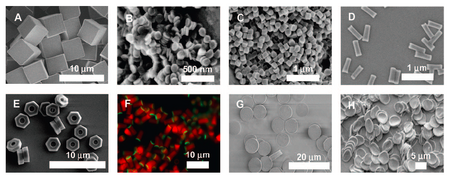
- Outstanding chemical and mechanical properties of PFPE-based elastomers enables fabrication of precise micro- and nano-scale particles (from 20 µm to 20 nm in size) with different shape (from spherical to cylindrical, to toroidal, etc.).3,8,9 PRINT patterning technique allows unmitigated physicochemical properties of synthesized particles during patterning process. This method of replication is amenable to have a great impact on not only material studies but also biomedical research and clinical applications.
PRINT Procedure
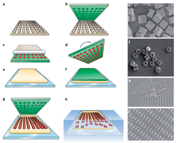
- Silicon Master Generation: Standard photolithrographic technique is used to create silicon wafer (with micro- and nanosized features) that becomes the master template for later patterning process. (Fig.1a)
- PFPE Mold Generation: Liquid PFPE precursor is poured on top of the silicon master to evenly spread all over the template. This wetting cover of PFPE is then photo-cured to form an elastomeric mold with negative display of the designed features set on the master. (Fig.1b)
- PFPE Mold Filling: Pre-particle liquid then fills into the negative mold using roll-to-roll technique that utilizes Myer rod casted with high-surface-energy counter sheet, for example poly(ethylene terephthalate) (PET), to generate a uniform surface of particles. The capillary forces trap the particles inside the mold cavities and the rest of the particle solution is removed by sticking to the high-surface-energy PET sheet (Fig.1c).
- Particle Solidification: Liquid pre-particles are then solidified with different methods (eg., thermal effect, UV irradiation, solvent evaporation, lyophilization, etc.)
- Pre-particles Settling: Heat and pressure are applied to detach the counter sheet off from the particles surface. Liquid particles are trapped and maintained inside the mold cavities by capillary forces while counter sheet is peeled away.
- Particles Solidification: Liquid pre-particles are then solidified with different methods (eg., thermal effect, UV irradiation, solvent evaporation, lyophilization, etc.)
- Particles Transfer: The PFPE mold containing solidified particles is turned over and placed on top of a harvesting film (e.g., poly(vinyl alcohol), polyvinylpyrrolidinone, cyanoacrylate) that lies on a glass substrate (Fig.1d-e). These materials are chosen as harvesting film due to: effective film formation allow better capturing agents; high adhesion onto glass, metal, plastic, etc., high water solubility or high solubility in other polar solvent. Heat and pressure are applied to detach the counter sheet off from the particles surface. When harvesting film is dried or polymerized, particles are trapped and maintained inside this adhesive layer while PFPE mold is peeled away (Fig.1g).
- Particles Collecting: Free floating particles is then collected by dissolving the adhesive layer with suitable solvent. The particles produced are typically in the range of 55 nm to 10000 nm.10 (Fig.1h)
Video introduces PRINT technique and procedure (by Liquidia Technologies, Inc.):
Retrieved from Orbital Tube
Applications of PRINT
Nanomedicine
With the advantage of PRINT technique to precisely control the size, shape, cargo, and surface modifications on particles, PRINT has been applied to nanomedicine. Conventional bench-work techniques to make nanoparticles, for example, liposomes, micelles, or polymeric nanoparticles cannot fully control consistent size and other characteristics of the nanoparticles, therefore PRINT nanoparticles have become a great tool for following studies:
- Cellular uptake mechanisms
- Biodistribution
- Pharmacokinetics
- Pharmacodynamics

In order to understand these behaviors, there are several features needed testing using PRINT particles:
- Particle size: 200 nm x 200 nm particles are uptaken at a rate of 1.2% of the cell population/minute while nonsymmetrical nanoparticles of 150 nm x 450 nm are uptaken at a rate of 5.2% of the cell population/minute.6
- Particle surface charge: positively charged nanoparticles are more effectively uptaken by cells than negatively charged nanoparticles.6,11
- Particle shape: cylindrical and rod-like PRINT particles are found to be internalized into nonphagocytic cells more efficiently with a wide range of size. Meanwhile normal nanoparticles that only depend on size are not effectively uptaken by cells if they are above 200 nm in size.6,11
- Particle modulus: Higher particle elasticity or flexibility enhances the circulation half-life of particles.11
- Surface chemistry modifications: 2-5 kDa poly(ethylene glycol) (PEG) coating on PRINT particles helps reduce opsonization, thus prolongs circulation of particles and enhances tumor accumulation.6,11 Modifications on the surface of particles with receptors or ligands also help specify target to pathological region, promoting drug delivery efficiency.11
Janus particles
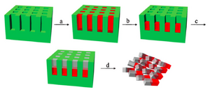
Janus particles are synthesized with two distinguished materials on each side of the particles. PRINT technique can improve the fabrication process by keeping the filling compositions in the same mold with multiple steps. This process can be done either horizontally or vertically due to the dimension of the mold features. In detail of how PRINT technique fabricates Janus particles, there are four major steps (example of vertical mold filling) (Fig. 3) 2:


- Into the mold cavities, the first monomer solution is filled. This solution is diluted with volatile solvent in advance and is photo-curable. (Fig.3a)
- After half of the solvent is evaporated, the rest of the first monomer is concentrated at the bottom of the mold, then is partially photo-cured with UV irradiation. At this state, even though the material is hard enough for second application of wet material without any phase mixing issue, this first monomer still maintains some photo-curable groups. (Fig.3b)
- The second material covers the rest of the mold cavities and both monomers are cured to completion under UV irradiation. The two materials are covalently bonding to each other. (Fig. 3c)
- Janus particles are then collected by the subsequent steps of standard PRINT process. (Fig. 3d)
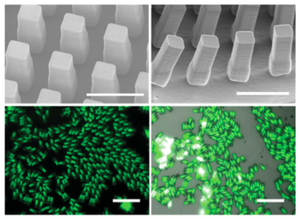
Janus particles made by PRINT method can be observed under scanning electron microscope (SEM) or fluorescence microscope (Fig. 4).
Drug Delivery
The impacts of PRINT on drug delivery are significant, as PRINT allows for sterile-filterable, mono-diverse, non-spherical particles to be constructed to contain a drug, which is notably important for respiratory drug delivery.12 Additionally, PRINT allows for the construction of particles used for delivering proteins, oligonucleotides, RNA, antigens, therapeutics, and immunostimulants.10, 12-13 For the purpose of vaccines using microparticles, the compatibility of the antigens and microparticle must be considered to prevent any denaturation which would hinder a humoral immune response.10 Furthermore, the particles manufactures in the PRINT process do not interfere with protein functionality, which allows targeted delivery of specific antibodies.10 Microneedle patches are an emerging use of drug delivery, which use an array of microneedles to pierce the skin and allow a drug to enter the body while being minimally invasive, especially compared to traditional needles and other methods of injection.10 More research needs to be performed but current studies already show promising results for the future of using PRINT to manufacture the micro and nano particles used for modern drug delivery.
References
1. Petros, R. A. & Desimone, J. M. Strategies in the Design of Nanoparticles for Therapeutic Applications. (2010).
2. Desimone, J. M. & Wang, J. Particle Replication in Non-wetting Templates : a Platform for Engineering Shape- and Size-specific Janus Particles. 90–107.
3. Gratton, S. E. A. et al. Nanofabricated particles for engineered drug therapies : A preliminary biodistribution study of PRINT TM nanoparticles. 121, 10–18 (2007).
4. Rolland, J. P., Hagberg, E. C., Denison, G. M., Carter, K. R. & Simone, J. M. De. High-Resolution Soft Lithography: Enabling Materials for Nanotechnologies**. 5796–5799 (2004).
5. Masciullo, C., Sonato, A., Romanato, F. & Cecchini, M. Perfluoropolyether ( PFPE ) Intermediate Molds for High-Resolution Thermal Nanoimprint Lithography. 1–9 (2018).
6. Gratton, S. E. A. et al. The Pursuit of a Scalable Nanofabrication Applications. 41, (2008).
7. Zanini, M., Isa, L., Maloney, R. C. & Hall, C. K. Fabrication of multiphasic and regio-specifically functionalized PRINT ® particles of controlled size and shape. 0–16 (2009).
8. Petros, R. A., Ropp, P. A. & Desimone, J. M. Reductively Labile PRINT Particles for the Delivery of Doxorubicin to HeLa Cells. 5008–5009 (2008).
9. Rolland, J. P. et al. Solvent-Resistant Photocurable “ Liquid Teflon ” for Microfluidic Device Fabrication. 2322–2323 (2004).
10. Beletskii, A.; Galloway, A.; Rele, S.; Stone, M.; Malinoski, F. Engineered Print® Nanoparticles for Controlled Delivery of Antigens and Immunostimulants. Human Vaccines & Immunotherapeutics 2014, 10 (7), 1908–1913. https://doi.org/10.4161/hv.28817
11. Perry, J. L., Herlihy, K. P., Napier, M. E. & Desimone, J. M. Specific Nanoparticle Theranostics. 44, (2011).
12. Chakraborty, A.; Patni, P. A Review on Microfabricated Engineered Particle Systems for Drug Delivery-PRINT. International Journal of Advanced Information Science and Technology 2014, 3 (1). https://doi.org/10.15693/ijaist/2014.v3i1.62-66.
13. Gratton, S. E. A.; Pohlhaus, P. D.; Lee, J.; Guo, J.; Cho, M. J.; DeSimone, J. M. Nanofabricated Particles for Engineered Drug Therapies: A Preliminary Biodistribution Study of Print™ Nanoparticles. Journal of Controlled Release 2007, 121 (1-2), 10–18. https://doi.org/10.1016/j.jconrel.2007.05.027
