Microfluidic Fuel Cells - Md Anisur Rahman
What are microfluidic fuel cells?

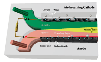
Microfluidic fuel cells (MFCs) represent a special type of electrochemical power generator that operates on a small scale, typically in the microliter to milliliter range, and can be integrated into a microfluidic chip. An MFC is a device that converts chemical energy from fuel into electrical energy, using a microfluidic system to transport the fuel and oxidant to the electrodes instead of conventional polymeric membranes.[1] MFCs are also often known as laminar-flow fuel cells or membrane-less fuel cells. Figure 1 shows a schematic of an MFC.
The basic principle of a microfluidic fuel cell is similar to that of a conventional fuel cell. It consists of two electrodes, an anode and a cathode, separated by an electrolyte. The fuel is introduced at the anode, where it is oxidized to generate electrons and protons. The electrons flow through an external circuit to the cathode, where they combine with the protons and the oxidant to form water. Microchannels or microchannel networks, which feature a substantially higher surface-area-to-volume ratio than conventional fuel cells, are used to feed the fuel and oxidant to the electrodes that ensure their quick and efficient transport to the electrode surface, increasing power production and efficiency.
Since its first fabrication in 2002 by Ferrigno et al., MFCs have been the subject of research and development for the past two decades, and they have been targeted primarily for use in portable electronics.[2] This is because microfluidic fuel cells offer a number of advantages over traditional fuel cells, such as their compact size, lightweight, and ability to operate on a wide range of fuels.
Advantages
Microfluidic fuel cells are particularly useful in applications where miniaturization is critical, such as in portable electronic devices, medical implants, and lab-on-a-chip systems [2]. They offer several advantages over conventional fuel cells, including lower cost, faster response time, and improved energy density. Because of their small size, microfluidic fuel cells can be integrated into portable electronic devices, such as cell phones, laptops, and other mobile devices, to provide power on the go.
In addition to their use in portable electronics, microfluidic fuel cells are also being explored for other applications, such as medical and implantable devices, where their small size and biocompatibility make them an attractive option. [1]
Disadvantages
One of the challenges of MFCs is achieving high power densities, since the small size of the cell limits the amount of fuel that can be introduced. Another challenge is precise controlling of the flow of fuel and oxidants to avoid crossover, which can be difficult in a small-scale system. The term "fuel crossover" refers to the unintended movement of fuel (hydrogen molecules, not hydrogen ions), from the anode to the cathode, across the electrolyte. With this in mind, fuel crossover and internal current can be viewed as elements that are "stolen" or "lost" from the external (load) current. Nevertheless, with the continuing research on and advancement of improving the performance and efficiency of microfluidic fuel cells, they have the potential to be a promising alternative to conventional fuel cells in certain applications.
Classification of MFCs
Based on reactant species: For an MFC to operate, it requires three main reactants, such as fuel, oxidant, and supporting electrolyte. The fuel is the energy source that will get oxidized to produce electrons. The oxidant is the electron acceptor that will accept the electrons and complete the electron transfer process. The supporting electrolyte helps to conduct the charge between the anode and cathode. MFCs can use a variety of different fuels, including gaseous fuels like hydrogen, hydrocarbon vapor, and ammonia, as well as liquid fuels like vanadium, alcohol, and formic acid. These fuels can be dissolved in the anolyte or stored in a separate fuel reservoir outside of the cell.[1]
Overall, the choice of reactants used in an MFC will depend on the specific mission profile and requirements of the application. Different fuel types may have different energy densities, operating temperatures, and other characteristics that may make them suitable for a given application. The choice of oxidant used in a reaction can depend on several factors, including the type of reaction, the desired outcome, and the specific conditions of the system. In some cases, gaseous oxidants like oxygen or air may be preferred for aerobic conditions, while in other cases, aqueous oxidants like H2O2 or KMnO4 may be used in anaerobic conditions. Ultimately, the choice of oxidant will depend on the specific needs of the reaction and the system in which it is being performed.
The supporting electrolyte carries electrically charged particles from one electrode to the other. A strong acid, such as H2SO4, or strong alkaline, such as KOH, is commonly used as a supporting electrolyte to ensure high ionic conductivity, depending on the fuel and oxidant's stability in the chosen medium. The acid-alkaline dual-electrolyte configuration is becoming popular due to its improved voltage and power output. This configuration generates a higher equilibrium cell voltage than a single electrolyte due to the more positive cathodic potential in an acidic environment and more negative anodic potential in an alkaline electrolyte.[1]

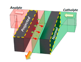
Based on flow configuration: It is important to note that MFCs use laminar flow, which is only possible at the microfluidic scale. MFCs can be categorized into three main types based on their flow configurations: single-flow, double-flow, and triple-flow, as shown in Figure 2.
Single-flow MFCs typically have a rectangular channel with one inlet and one outlet and use only one electrolyte. The flow configuration can either be a gaseous fuel and oxidant from outside the channel or a mixed fuel and oxidant in one electrolyte. These types of MFCs are suitable for reactants that can serve as both fuel and oxidant, such as hydrogen peroxide.[3] These types of MFCs face no issues with crossover, but presumably are energy density limited because of the use of gaseous materials.
Double-flow MFCs are currently the mainstream of MFC development and can be further divided into two categories: co-flow and counter-flow. [1] In co-flow MFCs, the anolyte and catholyte make contact with each other and flow in parallel towards the outlet after settling their electrodes, and the direction of diffusive crossover is orthogonal to the direction of advective flow. In contrast, counter-flow MFCs place their electrodes before the contact of the electrolytes, which minimizes the crossover issue as it is now parallel to fluid flow. Therefore, counter-flow MFCs can tolerate much lower electrolyte flow rates and obtain higher fuel utilization. However, they encounter higher ionic resistance and generally have lower performance due to the longer ion diffusion distance, especially for the part of the electrode located away from the central channel.[4]
Triple-flow MFCs add an extra flow of electrolyte between the anolyte and catholyte to further minimize their mixing. This reduces the crossover issue even further but increases the electrolyte storage and system complexity.[5]
Overall, the flow configuration of MFCs plays an important role in their performance and efficiency. Different types of MFCs have their advantages and disadvantages, and researchers continue to explore and develop new configurations to improve their performance.

Based on electrode structure: The two electrode structures commonly used in MFCs are 2D flow-over electrodes and 3D flow-through electrodes. The 2D flow-over electrode (as shown in Figure 2) is a flat electrode that is placed above the electrolyte, and the electrolyte flows over its surface. The 3D flow-through electrode (Figure 3), on the other hand, is a porous electrode that allows the electrolyte to flow through it.
The flow-over electrode design has the advantage of allowing smooth electrolyte flow with minimal resistance, which helps to maintain high power output. However, the limited contact between the electrode surface and the electrolyte leads to poor fuel utilization, which limits the efficiency of the MFC.
The flow-through electrode can overcome this limitation by allowing better contact between the electrode surface and the electrolyte. This leads to improved fuel utilization and higher MFC efficiency. [6] However, the preparation of 3D flow-through electrodes is more complex and time-consuming than that of 2D flow-over electrodes.[5]
Type of fuels used in MFCs
The MFC performance, such as reversible cell voltage, reaction kinetics, and energy density are largely determined by the type of fuel used. To date, MFCs have been demonstrated to operate using a number of fuels, including vanadium ions, formic acid, methanol, ethanol, hydrogen, hydrogen peroxide, glucose, and glycerol.[1,7] Among them, formic acid and methanol are the most popular fuels in MFC study.[1]
Type of catalyst used in MFCs
The choice of catalyst plays a significant role in determining the cost of MFCs. To date, noble metals like Pt, Pd, and Ru are the preferred choices for most fuels, although their high cost makes it challenging to produce cost-effective MFCs.[8] One way to reduce the cost of these catalysts is to use carbon support or alloy them with other non-noble metals. This approach can help reduce the amount of noble metals needed for MFCs while maintaining their performance. For vanadium fuel, low-cost carbon is sufficient for achieving high cell performance, and for nitrogenous fuels like ammonia and urea, Ni is a suitable choice of catalyst.[1]
Overall, the choice of catalyst is a critical factor in determining the cost of MFCs. By using cost-effective materials and exploring alternative catalysts, MFCs can be made more affordable and accessible for practical applications.
Microfluidic biofuel cells

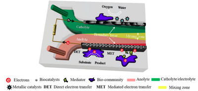
Microfluidic biofuel cells are a type of fuel cell that uses biocatalysts, such as enzymes or microorganisms, to convert the chemical energy stored in organic compounds into bioelectricity through a series of reactions. These biocatalysts are attached to the surface of cathodes, anodes, or both (as shown in Figure 4), and are capable of digesting a variety of fuels, including single fuel molecules and mixed fuels such as human blood, marine sediment, and wastewater.[9]
To extract the electrons from these fuels, the biocatalysts must undergo an extracellular electron-transfer (EET) process, which involves two pathways. [10] Some electrons go through the direct electron-transfer process, which occurs via direct outer membrane protein-electrode assembles, conductive pili, or both. Other electrons are delivered by mediated electron-transfer processes, which occur through electron mediators such as flavins and quinones. These two processes can work together in the transport of electrons.
There are two types of microfluidic biofuel cells, depending on the biocatalysts used. Microfluidic enzymatic fuel cells use enzymes as biocatalysts, while microfluidic microbial fuel cells use microorganisms as biocatalysts. Both types of microfluidic biofuel cells have potential applications in areas such as medical devices, environmental monitoring, and portable power sources. The area was pioneered by Moore et al.,[11] and since then a few such MFCs have been reported, rendering it a potential area of research.
References
1. Wang, Y.; Luo, S.; Kwok, H. Y.; Pan, W.; Zhang, Y.; Zhao, X.; Leung, D. Y. Microfluidic fuel cells with different types of fuels: A prospective review. Renew. Sustain. Energy. Rev. 2021 141, 110806. https://doi.org/10.1016/j.rser.2021.110806
2. Ferrigno, R.; Stroock, A. D.; Clark, T. D.; Mayer, M.; Whitesides, G. M. Membraneless vanadium redox fuel cell using laminar flow. J. Am. Chem. Soc. 2002 124(44), 12930-12931. https://doi.org/10.1021/ja020812q
3. Tanveer, M.; Ambreen, T.; Khan, H.; Kim, G. M.; Park, C. W. based microfluidic fuel cells and their applications: A prospective review. Energy Convers. Manage. 2022, 264, 115732. https://doi.org/10.1016/j.enconman.2022.115732
4. Wang, Y.; Leung, D. Y.; Zhang, H.; Xuan, J.; Wang, H. Numerical and experimental comparative study of microfluidic fuel cells with different flow configurations: Co-flow vs. counter-flow cell. Appl. Energy 2017, 203, 535-548. https://doi.org/10.1016/j.apenergy.2017.06.070
5. Sun, M. H.; Casquillas, G. V.; Guo, S. S.; Shi, J.; Ji, H.; Ouyang, Q.; Chen, Y. Characterization of microfluidic fuel cell based on multiple laminar flow. Microelectronic Engineering 2007, 84(5-8), 1182-1185. https://doi.org/10.1016/j.mee.2007.01.175
6. Kjeang, E.; Djilali, N.; Sinton, D. Microfluidic fuel cells: A review. J. Power Sources 2009, 186(2), 353-369. https://doi.org/10.1016/j.jpowsour.2008.10.011
7. Kjeang, E.; Michel, R.; Harrington, D. A.; Djilali, N.; Sinton, D. A microfluidic fuel cell with flow-through porous electrodes. J. Am. Chem. Soc. 2008, 130(12), 4000-4006. https://doi.org/10.1021/ja078248c
8. Rashed, M. K.; Mohd Salleh, M. A.; Abdulbari, H. A.; Shah Ismail, M. H.; Izhar, S. The effects of electrode and catalyst selection on microfluidic fuel cell performance. ChemBioEng Rev. 2015, 2(5), 356-372. https://doi.org/10.1002/cben.201500007
9. Xie, X.; Yu, G.; Liu, N.; Bao, Z.; Criddle, C. S.; Cui, Y. Graphene–sponges as high-performance low-cost anodes for microbial fuel cells. Energy Environ. Sci. 2012, 5(5), 6862-6866. DOI https://doi.org/10.1039/C2EE03583A
10. Yang, Y.; Liu, T.; Tao, K.; Chang, H. Generating electricity on chips: Microfluidic biofuel cells in perspective. Ind Eng Chem Res '2018, 57(8), 2746-2758. https://doi.org/10.1021/acs.iecr.8b00037
11. Moore, C. M.; Minteer, S. D.; Martin, R. S. Microchip-based ethanol/oxygen biofuel cell. Lab Chip 2005, 5(2), 218-225. DOI https://doi.org/10.1039/B412719F
