User:Dan C. Wilkinson/Notebook/Physics 307L/8/11/10
Osciliscope Lab

SJK 14:41, 24 September 2010 (EDT)

This is a good primary notebook. Seems like the necessary information is there to reproduce much of the work. Good use of photos.
Start Up
SJK 14:37, 24 September 2010 (EDT)

Great that you include make and model number.
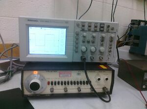
Pluged in Oscilloscope (Tektronix TDS 1002) to the (Wavetek model 182A) Function generator. From the SYNC OUT port on the generator to the CH 1 port on the oscilloscope. This produced noise and I quickly realized that I was in the wrong port. Had to use the LO (2V) 50ampout instead of SYNC out port on generator. Connection was made with RG-58c/U BNC cable.
Basic Measurments
Set frequency to ~300Hz, DC offset set to 0. Oscillosope measurment read 303.87Hz. "Zooming in" using the Volts/DIV allowed me to count divisions and multiply by 112mV per division. (8*112=896mV). Hitting the measure button also gave a display of 896mV (peak to peak). I noticed that, in square waves, there was a small discrepency between my estimated value and the measured value of the machine (this is an artifact of the fourier transform of sines/cosines to constants).
- Using grid Lines
This is as simple as using the Volts/div knob, adjusting the display amplitude to fill the screen, counting the gridsegments(8) and multiplying this value by the volts/gridline displayed voltage
- Using Cursors
Hit cursor button, sellect type (voltage), move cursors using position knobs, and add up absolute values of cursor values.
- Using Measure
Hit measure button, select type (peak-peak)
- Sine Wave
300.56Hz output, sine wave, DC offset = 0
Using the gridlines 1.056V
Using the cursors 1.045V
Using the measure function 1.06V
- Triangular Wave
300.56Hz output, triangular wave, DC offset = 0
Using the gridlines 1.056V
Using the cursors 1.045V
Using the measure function 1.04V
- Square Wave
300.56Hz output, square wave, DC offset = 0
Using the gridlines 1.088V
Using the cursors 1.077V
Using the measure function 1.16V
(discrepencies in measure function and cursor approx. may come from the osciliscope measuring the bottom tip left over from making the square wave by adding many sine waves)
Triggering
Hit trigger menu button. Selected type(edge). Noticed that triggering can happen on a rising or falling slope. The machine will start recording when it detects a rising or falling slope. Noticed that must have cursor within amplitude of wave for osciliscope to register and record the wave (this may be able to factor out noise in an experament when you dont want to record lower voltages. The type of triggering didnt seem to matter (between pulse and edge) though the video option caused a noise like display.
AC Coupling
1. Applying a large DC voltage tends to shift the sine wave up/down if in DC coupling mode. Noted that the phase seems to shift but this can be explained by the change in where the triggering happens. This addition of DC current does not apparently change the frequency or the amplitude of the wave. AC coupling mode does not seem to allow the addition of the DC current therefore messing with the DC offset has no real effect on the wave. However Large DV Voltages can cause some deflection of the waves when in AC Coupling mode.
Square waves do not have a 0 slope when on AC coupling. This can be fixed by DC coupling.
2. The smallest change in DC Voltage can be detected when in DC coupling mode. This is accomplished by triggering at a certain(small) voltage. Or one may be able to zero out the wave and look for distortions.
3. Fall Time
My estimated fall time is 36ms
The measured fall time is 34.7ms
- To make these measurments I had to decrease the frequency to 12.5Hz. The Voltage was set to 8.4V. I was also in the AC coupling mode. Fall Time
[math]\displaystyle{ \tau = RC = 34.7ms }[/math]
SJK 14:42, 24 September 2010 (EDT)

I loved the extra exploration, keep it up!
Other Work
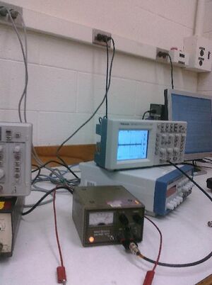
We (Tyler, Dr. Koch and I) decided to analyze the signal produced by an in house DC generator. We found strage periodic signals that were most likely caused by the transformation of AC to DC.
